26: COMPUTER LINK COMMUNICATION
« FC4A MICROSMART USER’S MANUAL » 26-3
Assigning Device Numbers
When assigning a unique device number of 0 through 31 to each CPU module for the 1:N computer link network, down-
load the user program containing the device number setting to each CPU module in the 1:1 computer link system, then the
new device number is assigned to the CPU module. Make sure that there is no duplication of device numbers in a 1:N
computer link network.
Communication Settings
When monitoring the MicroSmart operation or downloading a user program using WindLDR, make sure that the same
communication settings are selected for the CPU module and WindLDR, so that the computer communicate with the
MicroSmart in either the 1:1 or 1:N computer link system. To change the communication settings for WindLDR, access the
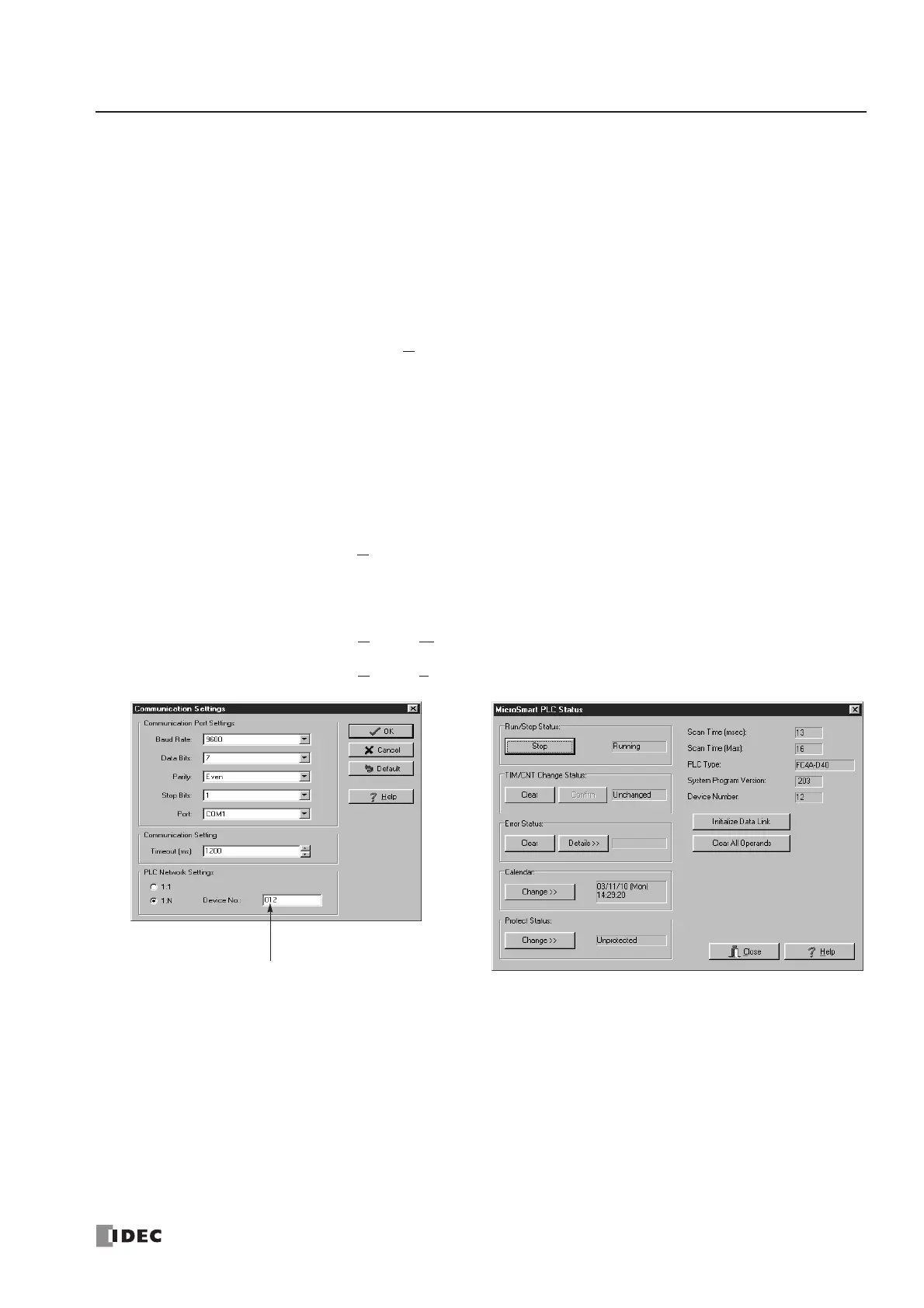
Communication Settings dialog box from the Configure menu as shown below.
When communicating in the 1:N computer link system for monitoring or downloading, select the device number of the
CPU module also in the Communication Settings dialog box.
Monitoring PLC Status
The following example describes the procedures to monitor the operating status of the MicroSmart assigned with device
number 12 in a 1:N communication computer link system.
1. From the
WindLDR menu bar, select Configure > Communication Settings. The Communication Settings dialog box
appears.
2. Under PLC Network Settings, click the 1:N button to select 1:N communication, and enter 12 in the Device No. field.
3. From the WindLDR menu bar, select Online > Monitor. The ladder diagram on the screen enters the monitor mode.
4. From the WindLDR menu bar, select Online > PLC Status. The PLC Status dialog box appears.
number to communicate with.
 Loading...


