EasyManuals Logo
Home>IDEC>Controller>FC4A-C24R2

IDEC FC4A-C24R2 User Manual

IDEC FC4A-C24R2
525 pages
To Next Page IconTo Next Page
To Previous Page IconTo Previous Page
Page #190 background imageLoading...
Page #190 background image
7: BASIC INSTRUCTIONS
7-6 « FC4A MICROSMART USERS MANUAL »
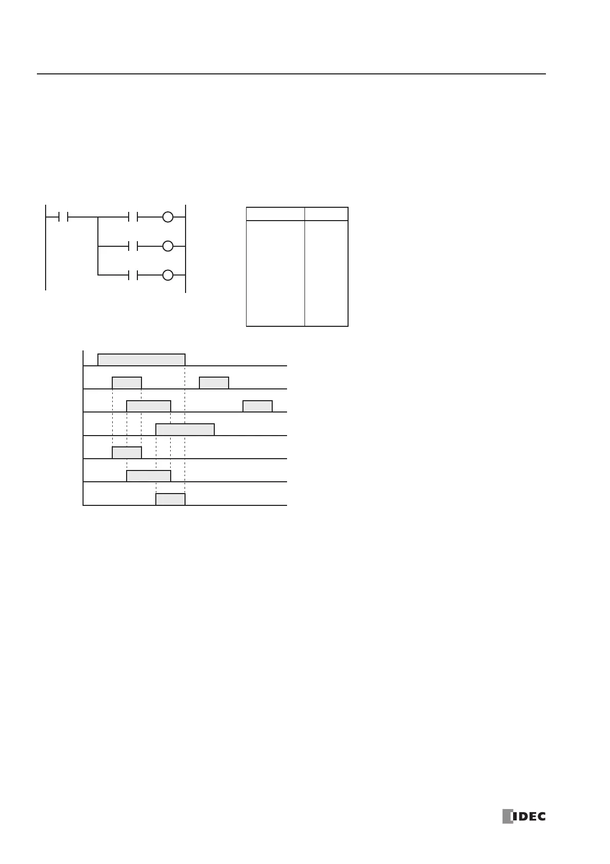
BPS (Bit Push), BRD (Bit Read), and BPP (Bit Pop)
The BPS (bit push) instruction is used to save the result of bit logical operation temporarily.
The BRD (bit read) instruction is used to read the result of bit logical operation which was saved temporarily.
The BPP (bit pop) instruction is used to restore the result of bit logical operation which was saved temporarily.
When using WindLDR, the user need not program the BPS, BRD, and BPP instructions. The circuit in the ladder diagram
shown below is converted into BPS, BRD, and BPP when the ladder diagram is compiled.
I0
I1
I2
Ladder Diagram
I0
ON
OFF
I1
ON
OFF
I2
ON
OFF
I3
ON
OFF
Timing Chart
Q1
ON
OFF
I3
Q2
ON
OFF
Q3
ON
OFF
When both inputs I0 and I1 are on, output Q1 is turned on.
When both inputs I0 and I2 are on, output Q2 is turned on.
When both inputs I0 and I3 are on, output Q3 is turned on.
BPS
BPP
BRD
Instruction Data
LOD
BPS
AND
OUT
BRD
AND
OUT
BPP
AND
OUT
I0
I1
Q1
I2
Q2
I3
Q3
Program List
Q1
Q2
Q3

Table of Contents

Questions and Answers:

Question and Answer IconNeed help?

Do you have a question about the IDEC FC4A-C24R2 and is the answer not in the manual?

IDEC FC4A-C24R2 Specifications

General IconGeneral
BrandIDEC
ModelFC4A-C24R2
CategoryController
LanguageEnglish

Related product manuals