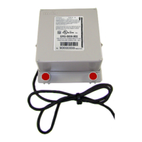
11. Gather the excess ERT module cabling into a
loop and use the cable tie to secure the gathered
cable to the pipe.
Adapter plate mounting configurations
Note: The notch at the top of the adapter plate (1) must always be at the top position. The
following illustrations show the various mounting configurations. The adapter plate mounting
screw locations are indicated (2).
45-degree angle with the
pipe running to the right
45-degree angle with the pipe
running to the left
Horizontal
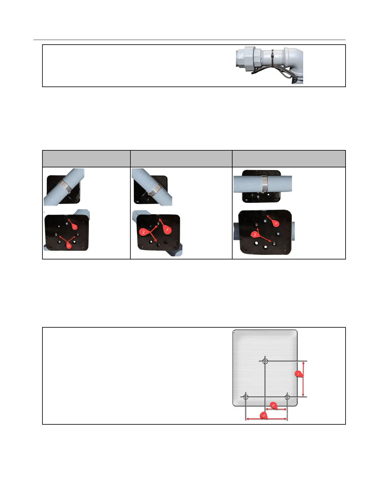
Mounting the remote gas module on a flat vertical
surface
Carefully select a mounting location free from electrical wires. The mounting location must
have the proper clearance to accommodate the 1-1/2-inch module mounting screws so
nothing is damaged by the drill or mounting screws. Use compatible mounting screws.
1. Drill three pilot holes in the mounting surface.
The drilled pilot holes for the two bottom screws
must be on a horizontal line.
1. 3 inches
2. 1-11/16 inches
3. 3-3/8 inches
Mounting the 100G Series Remote Gas ERT Module
100G Series Gas ERT Module Installation Guide, Remote Mount TDC-0824-017 11
Proprietary and Confidential
 Loading...