8. Close and latch the MPplus corrector door.
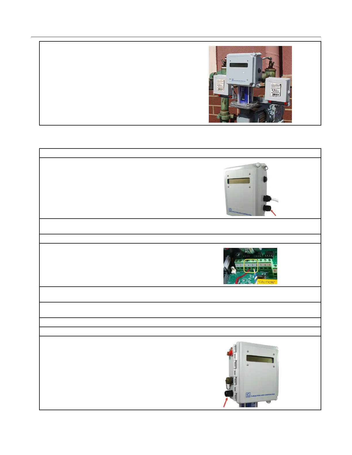
Connecting the 100G ERT module to the XARTU corrector
For XARTU-1 uncorrected reads:
1. Insert the flying leads from the remote ERT
module into the compression connector on the
right of the XARTU-1 corrector housing.
2. Pull the lead wires through the compression connector until there is adequate wire to reach the
K2 terminal port.
3. Tighten the compression connector.
4. Connect the red remote ERT module wire to
pin 4 of the K2 terminal port.
5. Twist the remote ERT module's blue and white wires together and connect the twisted blue and
white wires to pin 5 of the K2 terminal port.
6. Plug the MTA battery connector from the battery pack into the VBAT1 connector to supply power
to the XARTU-1 corrector.
7. Close and latch the corrector door.
For XARTU-1 corrected reads:
8. With the XARTU door open, insert the flying
leads from the remote ERT module into the
compression connector on the left of the
corrector's housing.
Specific Meter Manufacturer Installation
100G Series Gas ERT Module Installation Guide, Remote Mount TDC-0824-017 21
Proprietary and Confidential
 Loading...