7. Connect the uncorrected module wires to the Input Switch Board UNC. VOL following the table
below.
Uncorrected ERT module connections
Mini-Max input switch board unc. vol. ERT module wire color
COM terminal Red
No terminal Blue*
No terminal White*
*Twist the blue and white ERT module wires together before connecting them to the Mini-Max
board. Tighten the terminal connection securely.
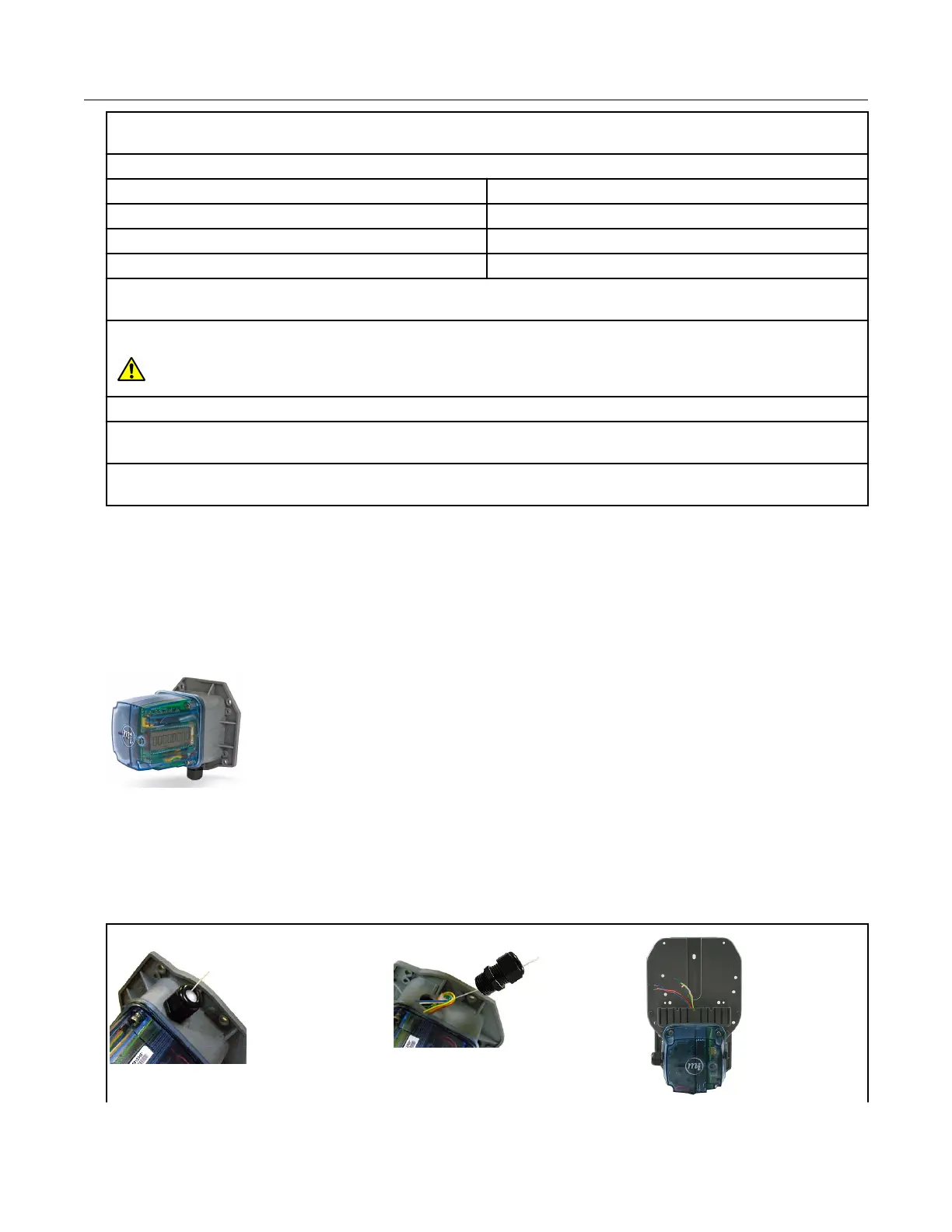
8. Tighten the large strain relief securely.
Warning: Do not crush the module through-cables when tightening the strain relief.
9. Re-install or reconnect the power or battery sources.
10. Close the instrument case and tighten the case screw securely. Replace any locks that were
removed for installation.
11. Install the remote ERT module. See Mounting the 100G Series Remote Gas ERT Module on
page 8.
Connecting the remote ERT module to the Honeywell TCI
The Honeywell Instruments Temperature Compensating Index (TCI) provides two Form-A
volume pulse outputs and one Form-B alarm output. These outputs are electronic switches.
The Form-A pulse outputs are configurable for compensated or uncompensated volume.
The Form-B output is for alarm output use only.
Connections to the three output pulse channels are completed using loose unterminated
wires (the individual wires from a cable) and gel-connectors. The TCI unit has six
unterminated wires that require six gel-connectors (Itron part number CON-0023-001) to
enable pulse connections to ancillary devices. Loose wires are located inside the gray
adapter plate behind the black strain relief fitting.
Specific Meter Manufacturer Installation
100G Series Gas ERT Module Installation Guide, Remote Mount TDC-0824-017 47
Proprietary and Confidential
 Loading...