Romet cable number 34-125-51
Cable pin ERT module wire
Correct Uncorrected Aux CC
6 White and blue
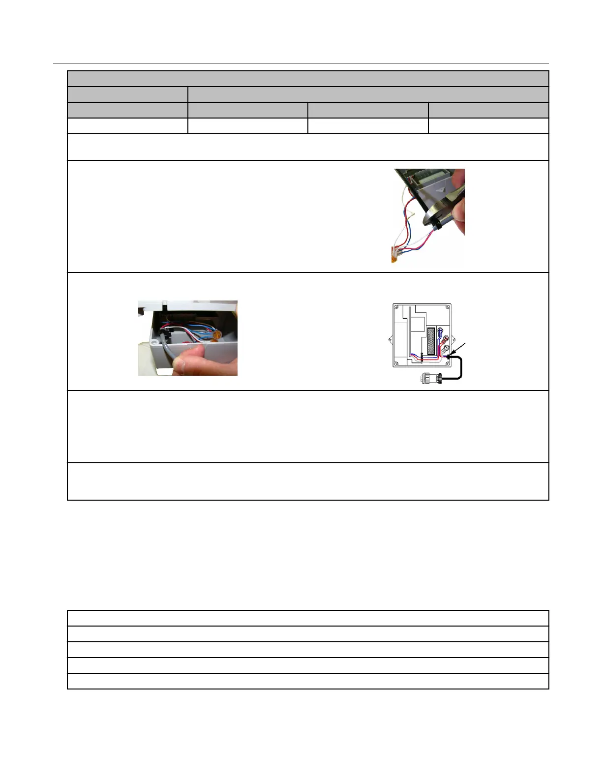
4. After the wire connections are completed, install a cable tie to the meter cable just below the
exposed colored lead wires on the cable insulation.
5. Remove the excess cable tie using a hand-
held side-cutter pliers. The cable tie performs as
a cable strain relief to mitigate the risk of
destructive tension on the lead wires.
6. Tuck the three gel connectors and cable tie inside the module housing, as shown in the following
placement illustration and schematic.
7. Install the remote ERT module backplate using the four screws previously removed from the
module and a Torx T-10 screwdriver.
Important: Verify that the cable tie and gel connectors are inside the module housing and the cable
extends out of the slot in the backplate. Torque the backplate mounting screws to 9 to 12 inch-
pounds.
8. Install the module on the wall or a pipe using the pipe installation kit (Itron part number
CFG-0005-003) or install the module on the Romet AdEM meter using the Romet ERT mounting
bracket (Romet part number 46-444-2).
Romet corrector programming and requirements notes
AdEM programming
Note: Meter setup requires confirmation of communication settings with the AdEM corrector.
Communication confirmation requires the RometLink software and the Romet
communication cable.
1. Install the RometLink software on your PC.
2. Connect the AdEM corrector communication cable to your computer and the AdEM corrector.
3. Add the AdEM meter to your Phone Book.
3.a Open the RometLink software and log on.
3. b From the Talk to Unit tab, select Check > All. Click Yes.
Specific Meter Manufacturer Installation
100G Series Gas ERT Module Installation Guide, Remote Mount TDC-0824-017 60
Proprietary and Confidential
 Loading...