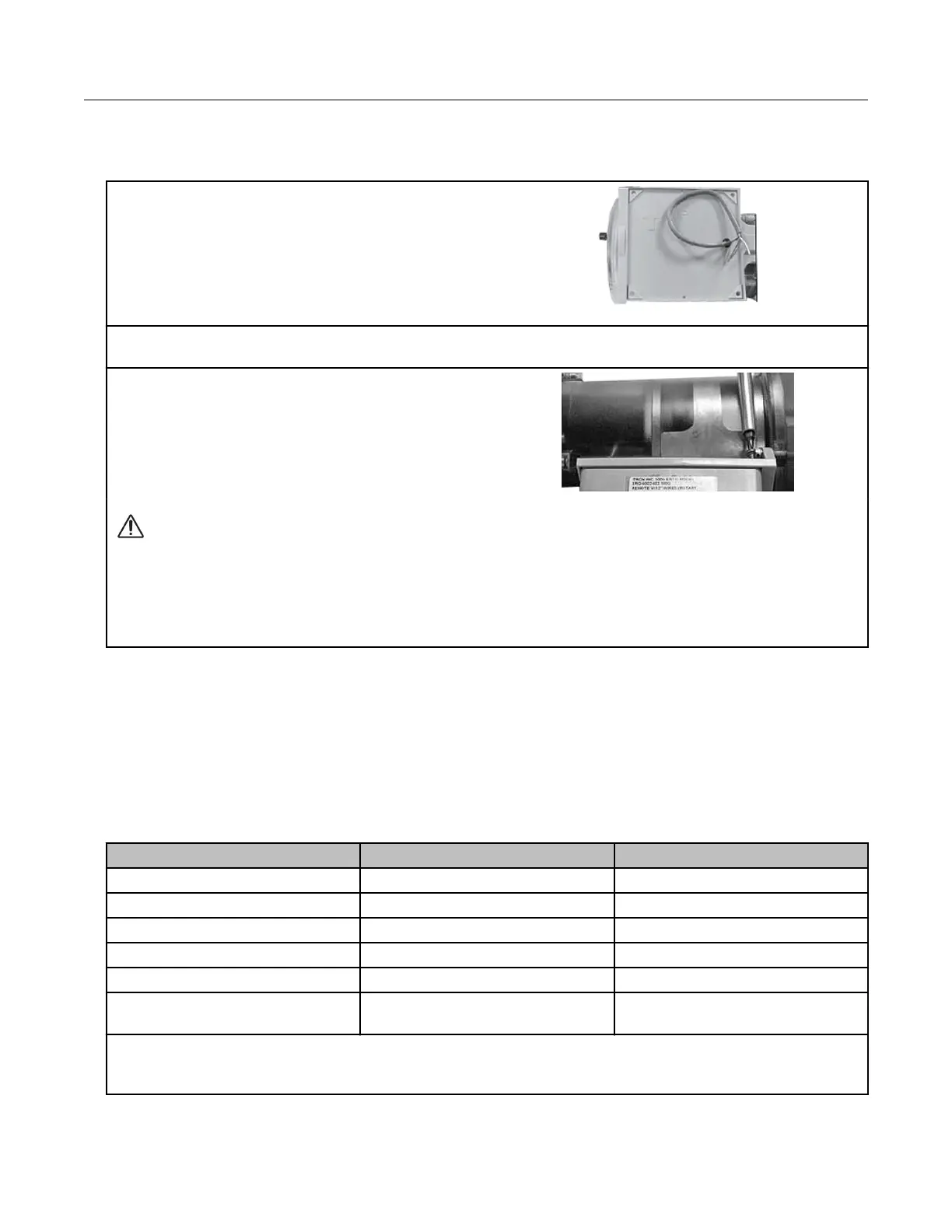
GE Oil and Gas ES3 or ETC ordered with the AMR-ready
mounting kit
1. Score (cut) the cable jacket surrounding the
ES3 or ETC wires and carefully remove the cable
jacket to expose the ES3 or ETC wires.
2. Connect the wires to the ERT module following the installation instructions in the GE Oil and Gas
meters with pulse output installation section.
3. Align the ERT module mounting holes with the
ES3 or ETC bracket mounting holes. Use a T15
Torx screwdriver to insert and tighten the
mounting screws. Tighten the screws in an
alternating pattern.
Caution: Upright vertical positioning is critical because:
• The 100G series modules are optimized for communication and require upright
mounting. Any other mounting position could result in reduced RF performance.
• The remote module tilt tamper sensor requires upright mounting. Any other mounting
position may cause issues with the module's tilt tamper detection.
GE Oil and Gas IMC/W2, or MC2 with the GE mounting bracket
kit
Note: This mounting option requires that you follow the installation instructions to attach the
meter maufacturer cable prior to completing this mounting option. This configuration
requires the GE mounting bracket kit available from GE Oil and Gas (GE part number
057783-000). The kit includes the listed materials.
Quantity Description GE Dresser part number
1 Mounting bracket 015951-000
1 Screw, 8-32 x 7/16-inch 000163-277
2 Screw, 8-32 x 3/4-inch 000163-282
3 Nut, 8-32 012829-005
4 Spacer, #10 053669-001
5 ERT module/bracket mounting
screw, M6 x 20 mm
013444-002
Important: The GE Dresser mounting bracket kit does not include the cable required to connect
the remote module to the Amphenal connector on the IMC\W2.
Specific Meter Manufacturer Installation
100G Series Gas ERT Module Installation Guide, Remote Mount TDC-0824-017 34
Proprietary and Confidential
 Loading...