4. Feed the lead and connector into the register
cover tower.
Note: Save any meter tags. You will re-install
them later in the installation process.
5. If you removed the register cover, replace the
cover using the four (4) 5mm mounting screws.
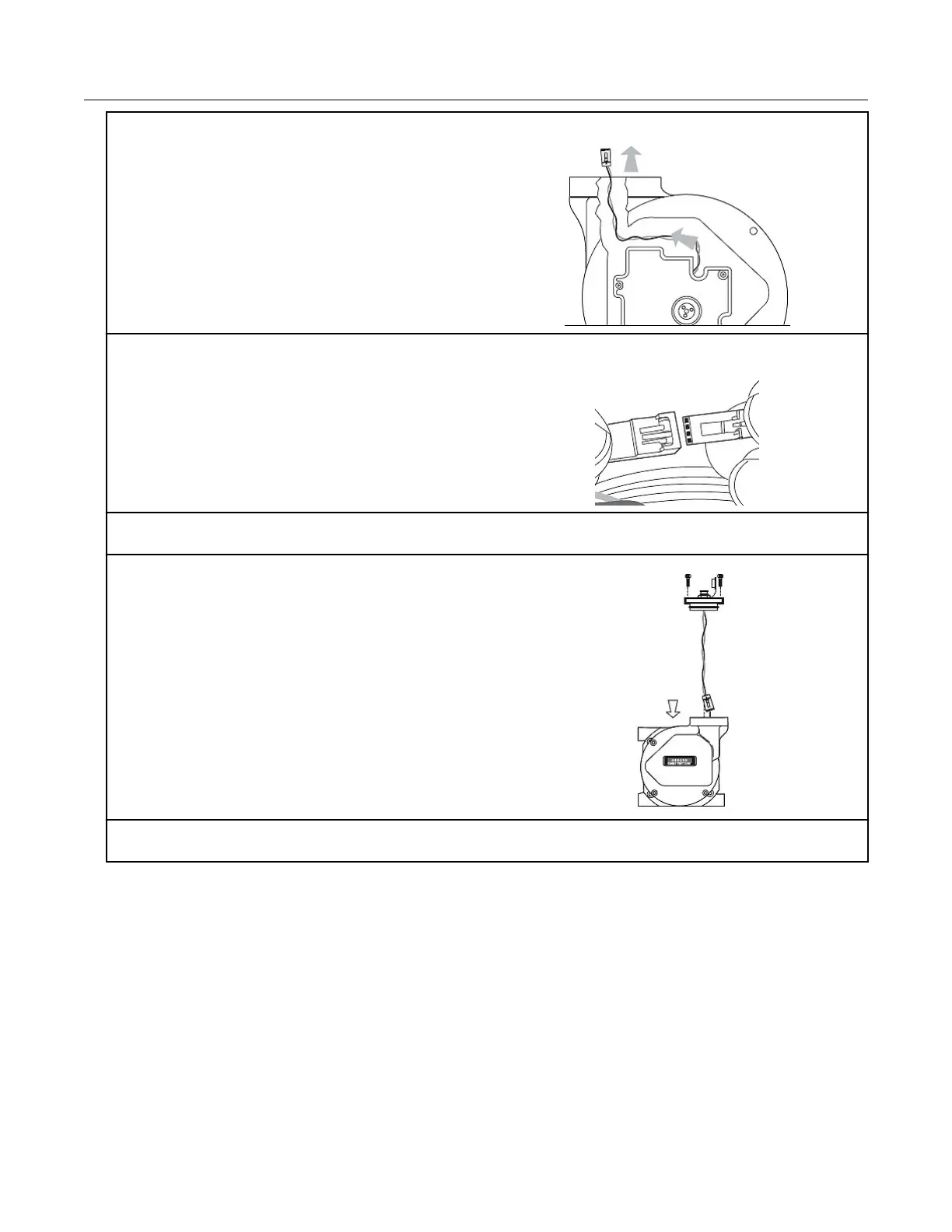
6. Attach the 4-pin male connector on the Elster American Meter adapter plate to the 4-pin female
connector inside the meter's tower. The connectors will slide together and latch.
7. Carefully push the connectors and wires into
the meter tower housing.
8. Lubricate the O-ring with O-ring lubricant and install the O-ring on the adapter plate. Insert the
adapter plate into the tower and tighten the two 5 mm screws.
Elster American mechanical and wiring installation
instructions
Note: Connection to an Elster American meter requires a cable interface compatible to an
Elster American RPM rotary meter.
Specific Meter Manufacturer Installation
100G Series Gas ERT Module Installation Guide, Remote Mount TDC-0824-017 28
Proprietary and Confidential
 Loading...