Meter model Meter notes 100G remote module type Itron part
number
ERT module notes
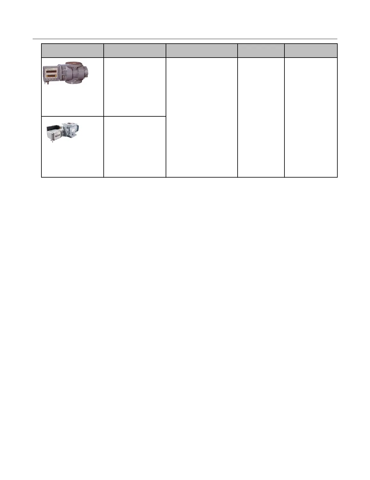
RM Series
Electronically
compensated meter
ECM2 600-56000
Meter must have
connector pin with
factory-installed pulse
output. Purchase correct
cable interface from
Romet.
AdEM
®
Series
Correctors including
AdEM-S
®
, AdEM-T
®
,
and AdEM
®
-PTZ
Must be configured to
350mS of output pulse
spacing and 30mS of
output pulse width.
Romet installation overview
100G ERT module installation with the Romet series correctors involves the following tasks.
1. Programming or verifying the that corrector is set up to work with the 100G remote ERT
module.
Programming requires a computer loaded with the RometLink software and a Romet
computer-to-corrector communication cable.
2. Connecting the ERT module to the corrector. Installation requires the following materials.
• Connection options, Cannon cable (part number: 43-035-40*) pigtail option
• Romet AdEM communication cable, available from Romet
• RometLink communication software, available from Romet
• 3 gel cap connectors, Itron part number CON-0023-001
• 3M crimping tool
• Torx T-10 screwdriver
• Remote ERT module with backplate and four included Torx screws (included with
module)
3. Mounting the remote ERT module (for more information, see Mounting the 100G Series
Remote Gas ERT Module on page 8. Select the mounting option appropriate for your
installation. Mounting options include:
• Wall mount on a sheet metal surface
• Pipe mount using the Itron pipe mount kit CFG-0005-003
• Custom Romet mounting (see Romet documentation for custom mounting)
4. Programming the 100G series remote ERT module. For programming information, see
100G Series Remote Module Programming on page 13. Programming requires an Itron
ERT programming device (for example, an FC300SR).
Specific Meter Manufacturer Installation
100G Series Gas ERT Module Installation Guide, Remote Mount TDC-0824-017 55
Proprietary and Confidential
 Loading...