1. Programming or verifying that the volume corrector is set up to work with the 100G
remote ERT module. Programming requires a computer communication cable.
2. Connecting the ERT module to the volume corrector. Completing the connections
requires a wire stripper and flat-tip screwdriver sized to tighten the terminal connections
on the Galvanic corrector.
3. Mounting the remote ERT module. Select the mounting option appropriate for your
installation. See Mounting the 100G Series Remote Gas ERT Module on page 8.
Mounting options include:
• Wall mount on a sheet metal surface
• Pipe mount using the Itron pipe mount kit CFG-0005-003
4. Programming the 100G series remote ERT module. For programming information, see
100G Series Remote Module Programming on page 13. Programming requires an Itron
ERT programming device (for example, an FC300SR).
100G series module configuration with the meter is dependent on your system application.
See the Galvanic corrector product documentation for configuration information.
Galvanic product mounting instructions
Note: See the Galvanic product documentation for custom mounting instructions.
Galvanic mechanical and wiring installation instructions
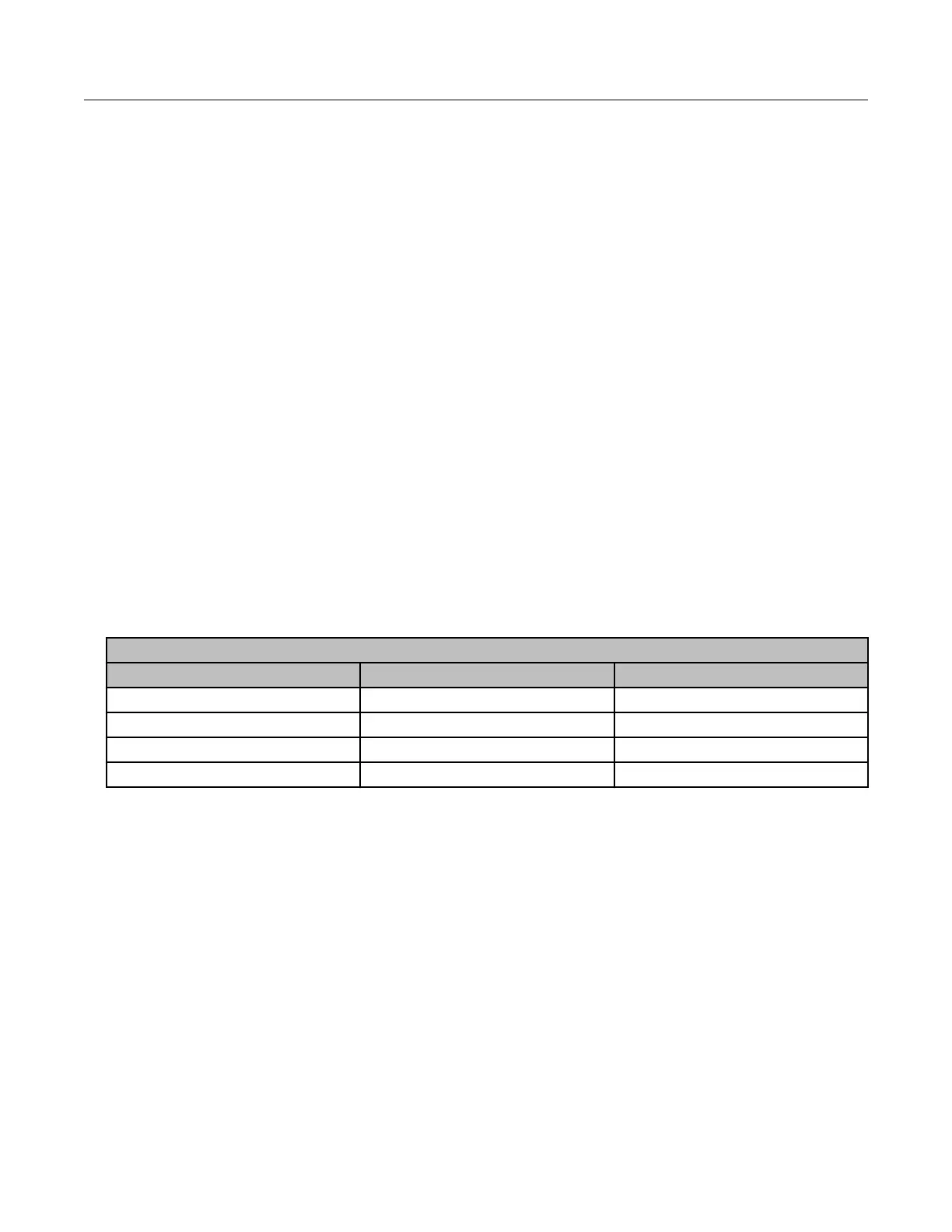
GAS Micro wiring connections
GAS Micro corrector P13 connection 100G ERT module wires
Pulse output1-C C1 Blue/white
Pulse output1-E C2 Red
Pulse output2-E C3
Pulse output2-C C4
Programming the Galvanic Gas Micro electronic volume
corrector
For more information about programming the Galvanic Gas Micro Electronic volume
corrector, see the GAS MICRO Operator's Manual, Galvanic part number MA1956. Contact
Galvanic Applied Sciences, Inc to obtain the operator's manual.
GE Oil and Gas meter installation
This section provides the instructions to install the 100G remote ERT module on the
following compatible GE Oil and Gas meters.
Specific Meter Manufacturer Installation
100G Series Gas ERT Module Installation Guide, Remote Mount TDC-0824-017 31
Proprietary and Confidential
 Loading...