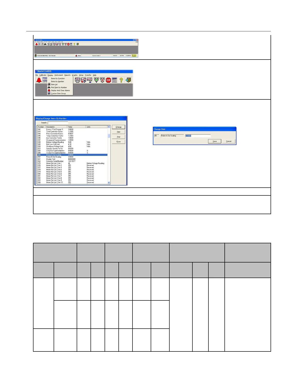
5. To view an Item configuration, select Display > Items by Number.
6. Verify the Honeywell instrument settings are correct. For example, Item number 56 must be set
to 2.0. If the setting is incorrect, click the Change button.
A Change Item pop-up provides the interface to
change the setting.
7. Enter the correct setting. Click Save.
8. Confirm that all settings match the settings required for the ERT module connected to the
Honeywell Instrument. For more information, see compatible ERT modules listed in Honeywell
Instrument installation on page 42.
Programming the Honeywell Instrument parameters
Program the Honeywell Instrument parameters following these Item Code Settings.
Channel A
Corrected
Volume
Channel B
Uncorrected
Volume
Channel C Pulse Output Spacing
Instru-
ment
Pulse
Output
Options
#56 #93 #57 #94 #58 #95 #115 #1014 #1015 Terminal Board
Connections/Wiring
ECAT
Pulse
Board
Ver-2(3)
Form A
2 Cor
Vol
2 Unc
Vol
2 Cor
Vol
1=1.0sec
2=2.0sec
or
4=0.5sec
Red ERT wire goes to
K
Blue and White ERT
wires go to Y
Connection must be
on same terminal
board channel (for
example, Ka/Ya;
kb/Yb; Kc/Yc)
Ka, Ya=Channel A
Kb, Yb=Channel B
Pulse
board
Ver-3(2)
FormC1
FormA
2 Cor
Vol
Mini with
Form A
main
board
Main
board
Type-2*
2 Cor
Vol
Specific Meter Manufacturer Installation
100G Series Gas ERT Module Installation Guide, Remote Mount TDC-0824-017 50
Proprietary and Confidential
 Loading...