Honeywell product mounting instructions
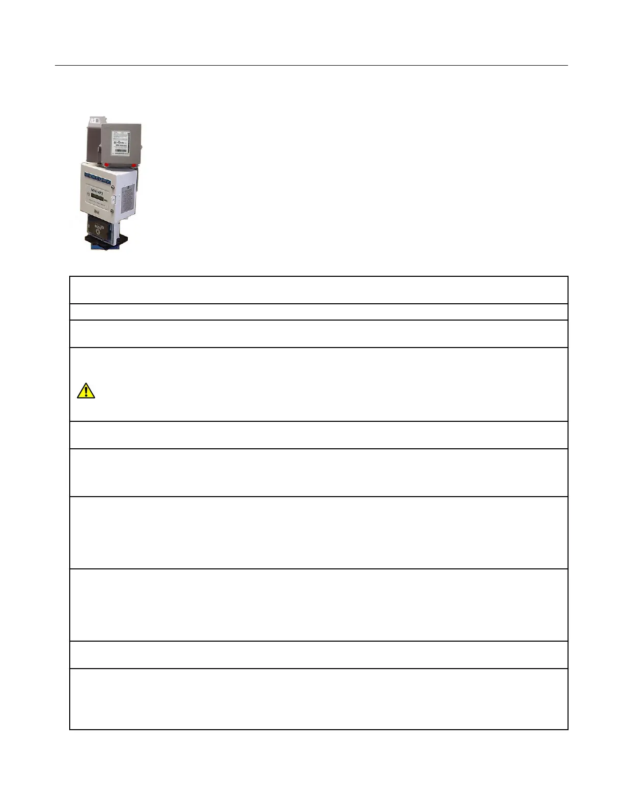
Two remote ERT modules mounted on a Honeywell Mini-Max Instrument
1. Place the Honeywell Instrument volume corrector in shutdown condition and disconnect all
power from the Mini-Max main board.
2. Remove the battery pack from the volume corrector and set it aside.
3. Remove the four screws from the main board and the board from the enclosure. Set the board
aside.
4. Remove the two hex screws from the input switchboard and the switchboard from the enclosure
and set it aside. You will re-install the switchboard later.
Warning: The battery pack, main board and switchboard may be damaged if left in the
Honeywell Instrument volume corrector while completing this installation.
5. Drill two 3/16-inch holes in the back of the Mini-Max enclosure as specified by the information
included in the kit. Remove any metal shavings from the enclosure.
6. Clean the remote ERT modules with the alcohol wipe where you will place the corrected and
uncorrected labels (included in the kit).
Note: Clean the ERT modules with the alcohol wipe to ensure good label adhesion.
7. Mount the module for corrected pulse outputs on the left bracket mounting space. Insert three
#8-32 x 1/2-inch screws in a triangular pattern. Install the top screw so the head of the screw is
approximately 1/8-inch from the ERT mounting bracket surface. Slide the module onto the screw so
the mounting lug fits securely onto the screw. If necessary, remove the module and make any
necessary adjustment to the screw depth to ensure a secure fit. Install the two bottom screws in an
alternating fashion.
8. Mount the module for uncorrected pulse outputs on the right bracket mounting space. Insert
three #8-32 x 1/2-inch screws in a triangular pattern. Install the top screw so the head of the screw
is approximately 1/8-inch from the ERT mounting bracket surface. Slide the ERT module onto the
screw so the mounting lug fits securely onto the screw. If necessary, remove the module and make
any necessary adjustment to the screw depth to ensure a secure fit. Install the two bottom screws
in an alternating fashion.
9. Route the module cables under the bracket edge and toward the rear of the Honeywell
Instrument.
10. Mount the ERT mounting bracket (Honeywell Instrument part number 22-1077, included in the
kit) onto the Mini-Max enclosure. Place a #8 metal flat washer followed by a rubber sealing washer
onto both #8-32 x 3/8-inch screws. Align the lower threaded holes in the mounting bracket with the
drilled enclosure holes and insert a screw/washer through the enclosure housing. Screws heads
must be inside the enclosure. Tighten both screws using a screwdriver.
Specific Meter Manufacturer Installation
100G Series Gas ERT Module Installation Guide, Remote Mount TDC-0824-017 44
Proprietary and Confidential
 Loading...