Channel A
Corrected
Volume
Channel B
Uncorrected
Volume
Channel C Pulse Output Spacing
Instru-
ment
Pulse
Output
Options
#56 #93 #57 #94 #58 #95 #115 #1014 #1015 Terminal Board
Connections/Wiring
Mini-AT
Kc, Yc=Channel C
JB29,JB3
0
&JB31
Jumpered
for
FormA*
2 Cor
Vol
2 Unc
Vol
Mini-Max All main
boards
2
Cor
Vol
2 Unc
Vol
1=1.0sec
or
2=2.0sec
TCI
FormA
main
board
2
Cor
Vol
2
Cor
Vol
Itron
100G
Itron
100G
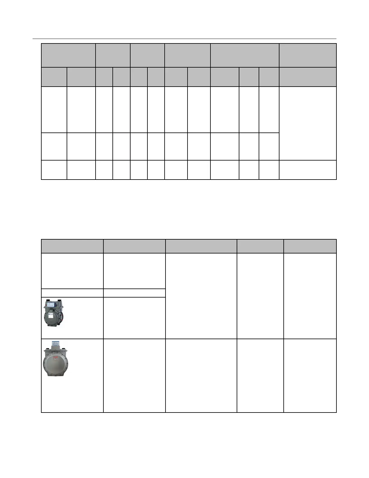
Itron meter installation
This section describes 100G series remote gas ERT module installation on Itron meter.
Installation information for the A-Series (1A, 305, 400, 675, and 1000) meters, see
Diaphragm Meter Installation on page 65.
Meter model Meter notes 100G remote module type Itron part
number
ERT module notes
1A Flat-face meter body
and 1A adapter plate
have interference fit
issue causing direct-
mount solution to be
non-compatible.
100G
100G Datalogging
100G Datalogging FN
100G DLS Datalogging
100G DLT Datalogging
ERG-5000-501
ERG-5002-501
ERG-5003-501
ERG-5006-501
ERG-5007-501
305 #2 flat-face meter
400
#3 flat-face meter
675, 1000
Front-mount index
100G
100G Datalogging
100G Datalogging FN
100G DLS Datalogging
100G DLT Datalogging
ERG-5000-501
ERG-5002-501
ERG-5003-501
ERG-5006-501
ERG-5007-501
Requires a thicker
gasket for magnet
hub to clear index
box.
1-hole gasket:
FAB-0014-001
2-hole gasket:
FAB-0014-002
4-hole gasket:
FAB-0014-003
Specific Meter Manufacturer Installation
100G Series Gas ERT Module Installation Guide, Remote Mount TDC-0824-017 51
Proprietary and Confidential
 Loading...