3. After adjustment, tighten the lock nut securely.
(1) Adjusting handle (2) Lock nut
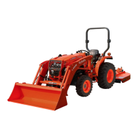
2.3 Adjusting the top link
The proper length of the top link varies according to the
type of implement being used.
1. Adjust the angle of the implement to the desired
position by shortening or lengthening the top link.
2. After adjustment, tighten the lock nut securely.
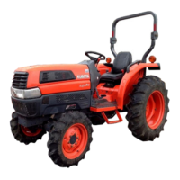
2.4 Adjusting the check chains
1. Adjust the turnbuckle to control the horizontal sway
of the implement.
(See Hydraulic control unit use reference chart on
page 87)
2. After adjustment, tighten the lock nut securely.
(1) Turnbuckle
(2) Lock nut
2.5 Dealing with the lower link holder
1. Holds the lower links with the lower-link-holder.
When operating the tractor without an implement, it
is necessary to lock the lower links to prevent them
from hitting the rear wheels of the tractor.
DRAWBAR
WARNING
To avoid personal injury or death:
• Never pull from the top link, the rear axle, or any
point above the drawbar. Pulling from the top
link, the rear axle, or any point above the
drawbar could cause the tractor to tip over
rearward.
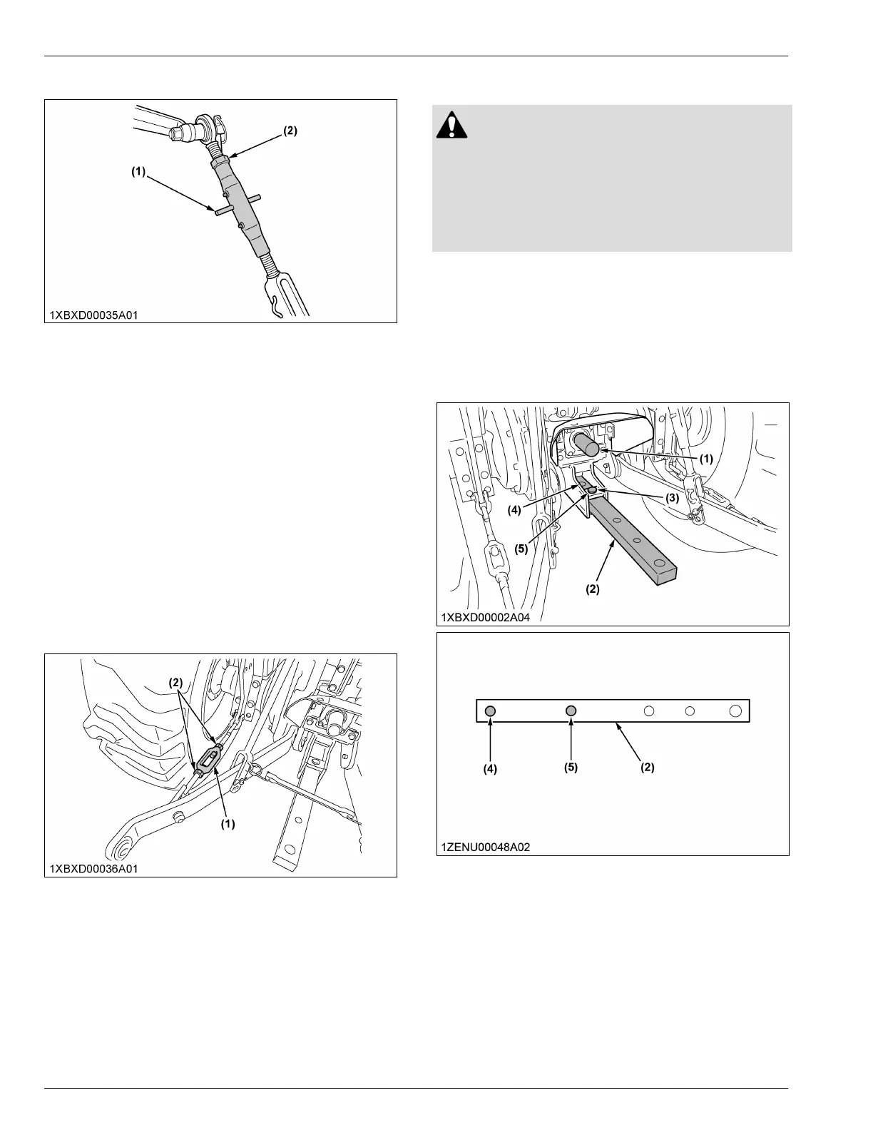
1. Adjusting the drawbar length
1. Adjust the length of the drawbar.
When towing an implement, it is recommended that
the (B) hole in drawbar to be utilized.
For information about the drawbar load, read the
IMPLEMENT LIMITATION TABLES on page 28.
(1) PTO shaft
(2) Drawbar
(3) Pivot pin
(4) Hole of drawbar (A)
(5) Hole of drawbar (B)
3-POINT HITCH AND DRAWBAR 3-POINT HITCH
 Loading...