Commissioning
Configuring the digital inputs and outputs
Setting the polarity
6
121
EDBCSXS064 EN 4.0
6.9 Configuring the digital inputs and outputs
6.9.1 Setting the polarity
The polarity can be set for each digital input and output. This determines whether the
input or output is HIGH active or LOW active.
The following are available:
ƒ 4 digital inputs (X6/DI1 ... DI4)
ƒ 1 digital output (X6/DO1)
ƒ 1 relay output (X25/BD1, BD2)
The GDC contains codes for setting the polarity of digital inputs and outputs in the
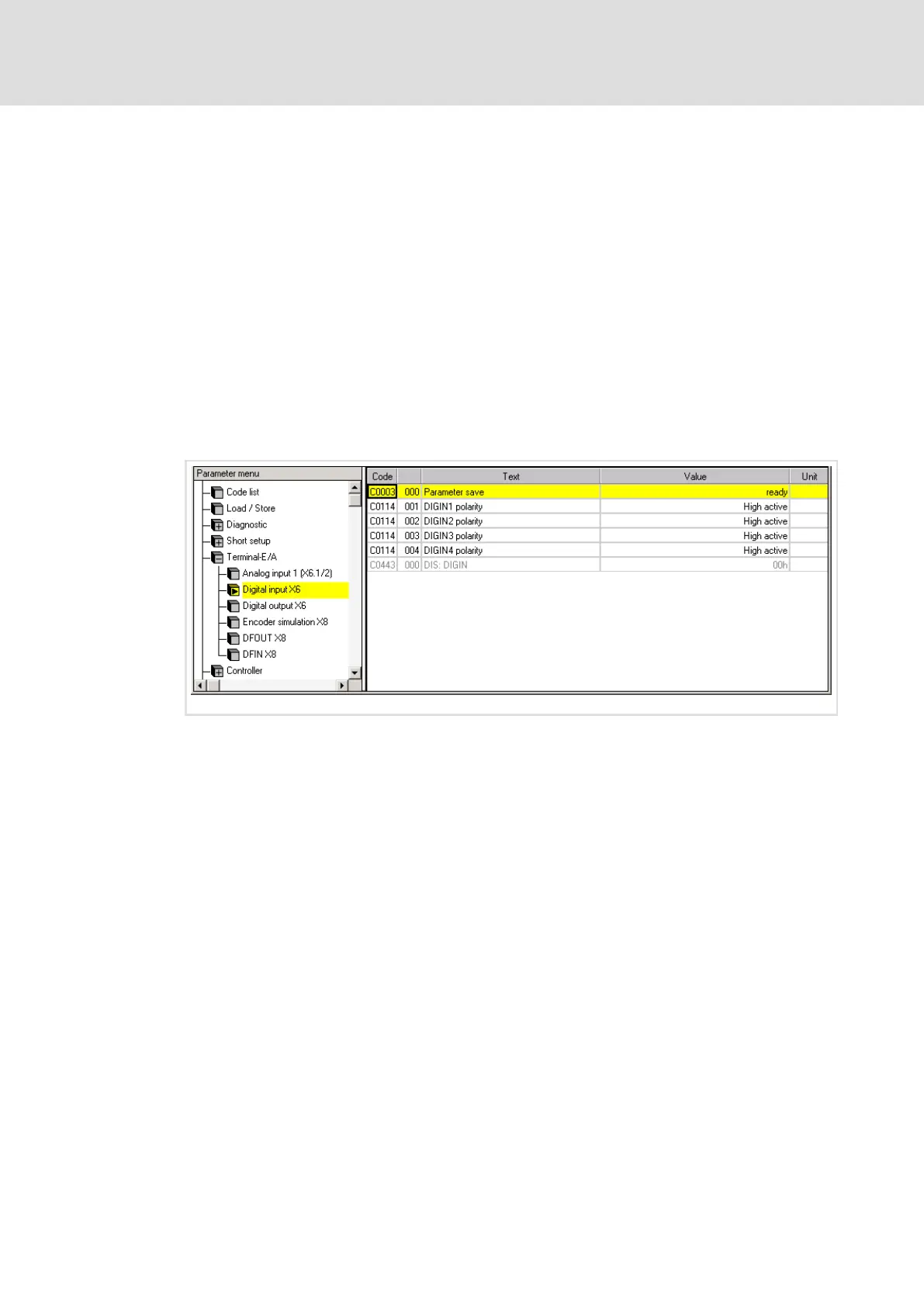
parameter menu under Terminal I/O:
ECSXA308
Fig. 6−7 GDC view: Setting of the polarity of digital inputs and outputs
6.9.2 Setting the direction of rotation
Based on the Lenze setting, the direction of rotation of the motor depends on
ƒ the sign of the speed setpoint.
ƒ the polarity of the digital inputs X6/DI1 and X6/DI2.
How to set the polarity/direction of rotation via C0114/x:
ƒ CW rotation
– C0114/1 = HIGH level active (X6/DI1)
– C0114/2 = LOW level active (X6/DI2)
ƒ CCW rotation
– C0114/1 = LOW level active (X6/DI1)
– C0114/2 = HIGH level active (X6/DI2)
ƒ Quick stop (QSP)
– C0114/1 = LOW level active (X6/DI1)
– C0114/2 = LOW level active (X6/DI2)
– See also page 144.
 Loading...


