Technical Information
16
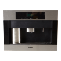
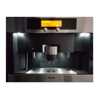
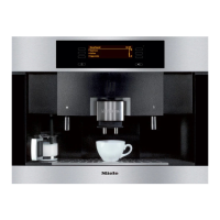
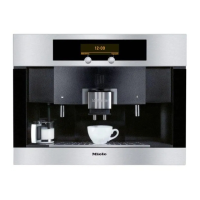
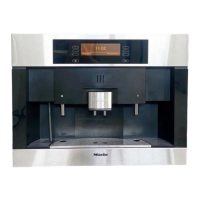
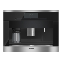
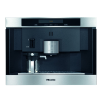
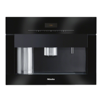
CVA 4062/CVA 4066/CVA 4068 Coffee Systems
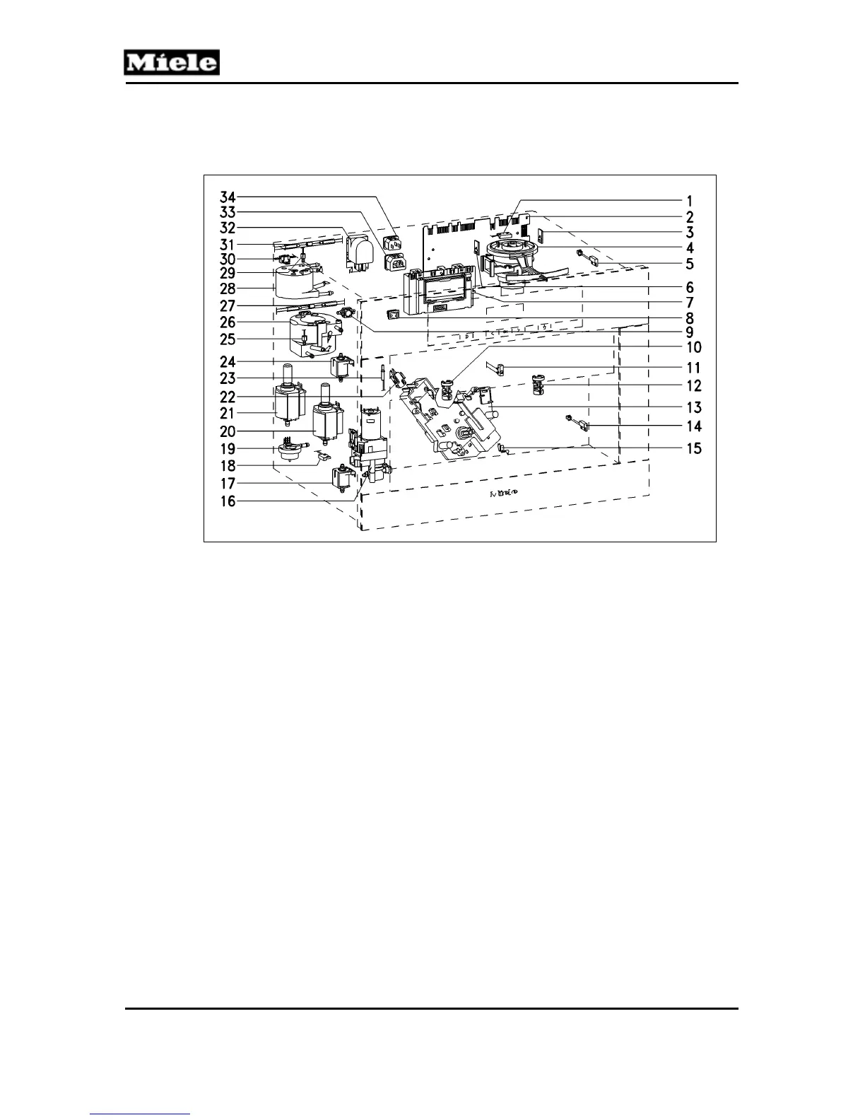
3 Electrical Components
3.1 CVA 4062, CVA 4068
Figure D-3: CVA 4062, CVA 4068 Component Layout
1
Switch, ground coffee funnel
18
Monitoring switch, grounds container
2
Power electronic (EPL)
19
Flow meter
3
Bean container sensor
20
Steam pump with temperature limiter
4
Grinder with temperature limiter
21
Coffee/hot water pump with temperature
limiter
5
Door contact switch
22
Step contact switch, grinding amount
6
Bean container sensor
23
Milk container present/level switch
7
Control/display electronic (EPWZ)
24
Steam solenoid
8
On/Off switch
25
Coffee/hot water NTC
9
Coffee/hot water heater temperature limiter
26
Coffee/hot water heater
10
Dispensing area light
27
Coffee/hot water heater fuse
11
Dispensing monitoring switch
28
Steam heater
12
Dispensing area light
29
Steam heater NTC
13
Brew unit drive with 2 brew unit position
switches and 1 brew unit presence switch
30
Steam heater temperature limiter
14
Float switch, water container, minimum level
31
Steam heater fuse
15
Drip tray level switch and drip tray sensor
(3 contact springs)
32
Interference suppression filter
16
Ceramic valve with valve step contact switch
and valve position switch
33
Not used
17
Hot-water solenoid
34
Main power socket
 Loading...