Technical Information
32
CVA 4062/CVA 4066/CVA 4068 Coffee Systems
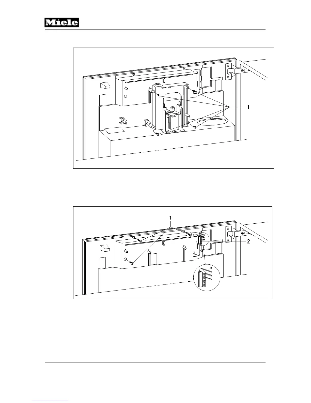
15. Remove the main dispenser.
Figure 025-4: Main Dispenser Retaining Screws
16. Remove the three control/display electronic cover retaining screws
(Figure 025-5, Item 1).
17. Disconnect the power electronic connection (Figure 025-5, Item 2).
18. Remove the control/display electronic cover.
Figure 025-5: Control/Display Electronic Cover and Power Electronic Connection
19. Disconnect all electrical connections from the control/display electronic; see Figure
025-6, Items 1, 2 and 3.
20. Carefully remove the housing containing the control/display electronic.
21. Unsnap at the bottom first, then at the top.
 Loading...