6 - 2 Defibrillator/Monitor Operator’s Manual
6.3 AED View
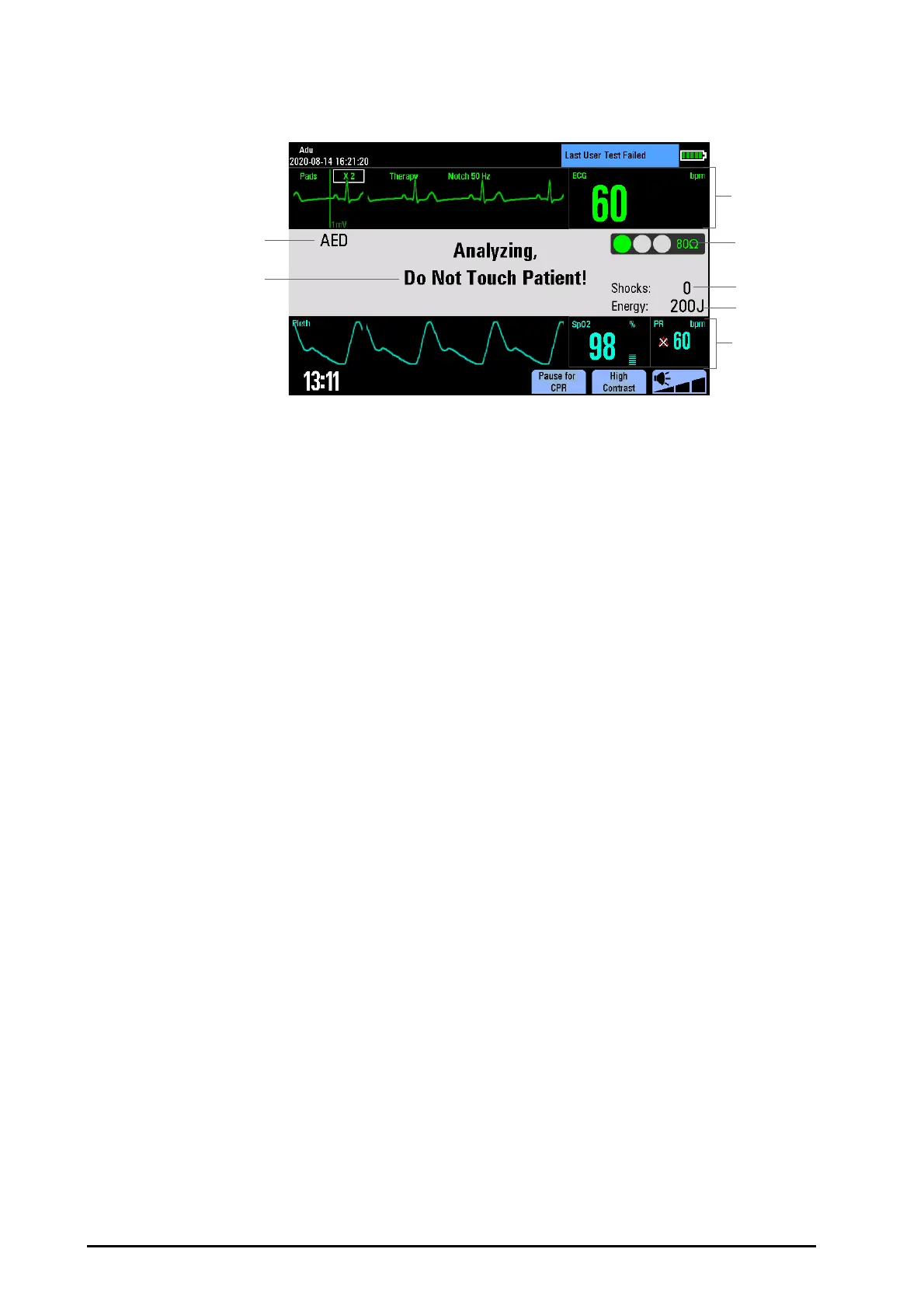
A typical screen in the AED Mode is shown below.
6.4 AED Procedure
Confirm that the patient is unresponsive, not breathing or not breathing normally. Then:
1. Prepare the patient and apply the electrode pads to the patient. For details, refer to 5.4.1Preparing the
Patient Skin and 5.4.3ECG Measurement with Electrode Pads.
2. Connect the electrode pads with pads cable, and then plug the pads cable into the therapy port.
Switch the Mode Select knob to AED. When the equipment enters the AED mode, it checks to see if the
electrode pads and pads cable are properly connected. If not, the message “Connect Pads Cable” or
“Apply Pads” will appear in the AED information area until corrective action has been taken.
3. Use the Navigation knob to switch the patient category between [Adu] and [Ped], if necessary. The default
energy level is automatically changed.
◆ For defibrillation of adult patients, recommended energy level for the first shock is 200 J.
◆ For defibrillation of pediatric patients, recommended energy level for the first shock is 50 J.
4. Follow the screen and voice prompts.
Once an ECG is detected through the electrode pads, the equipment automatically analyzes the patient’s
heart rhythm and warns you not to touch the patient. If a shockable rhythm is detected, the equipment
charges automatically.
You can switch on or off the voice prompt by selecting [AED Setup] from the Configuration Main menu or
adjust the volume of the voice prompts by pressing the voice volume soft key.
5. Press the Shock button, if prompted.
Once charging is completed, the equipment gives prompt “Do Not Touch Patient! Press Shock Button”.
Make sure no one is touching the patient, bed or any equipment connected to the patient. Call out clearly
and loudly “Stay Clear”. Then press the Shock button on the front panel to deliver a shock to the patient.
(1) Operating mode
(2) AED prompt message
(3) ECG parameter and waveform area:
This area displays HR numeric and one ECG waveform acquired from the electrode pads.
(4) Contact impedance indicator (configurable)
It indicates the impedance between the patient and electrode pads. For details, refer to
7.7Contact Impedance Indicator.
(5) Shock counter
(6) Selected energy
(7) Auxiliary parameter and/or waveform area
This area displays parameters from SpO
2
, NIBP or CO
2.
You can define the auxiliary
parameter by selecting [Manual Defib Setup] from the Configuration Main menu.
 Loading...