ECG/RESP Monitoring
11-31
INF: II, III, aVF and aVR
LAT: I, aVL, V5 and V6
Each ST group corresponds to an alarm limit. Once there is a parameter exceeding
the alarm limit of the group to which the ST parameter belongs, the alarm will be
triggered and the name of the group will flash.
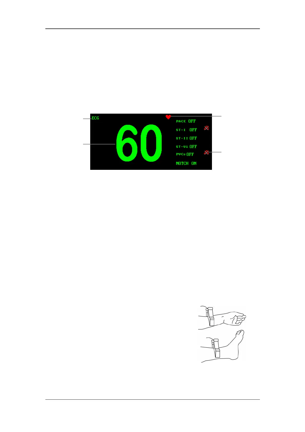
At the time of 12-lead monitoring, when you enter the large-font screen, the
parameter area will be displayed as shown below.
Figure 11-19 ECG parameters on large-font screen
The heartbeat indicator is displayed and flashes at the frequency of the patient’s
heartbeat. To the right of the HR numeric are the status or numerics of PACE, 3
groups of ST, PVCs and NOTCH.
11.6.2 Monitoring Procedure
For the preparation for the electrode placement, refer to 11.2 ECG Monitoring
Procedure.
Installing the electrodes
With reference to the American standard, the electrodes of the 10-leadwire ECG
cable shall be placed as follows for the 12-lead analysis:
RA (right arm) electrode;
LA (left arm) electrode;
RL (right leg) electrode;
LL (left leg) electrode;
Attach the four limb electrodes to the soft skin
of the hands/legs.
Attach the chest (V) electrodes to the following positions:
V1: On the 4th intercostal space at the right sterna margin;
ECG label
HR numeric
Alarm Disabled
icon
Heartbeat
indicator
 Loading...