OMNI 4000/7000 Operations and Maintenance Guide – Rev F
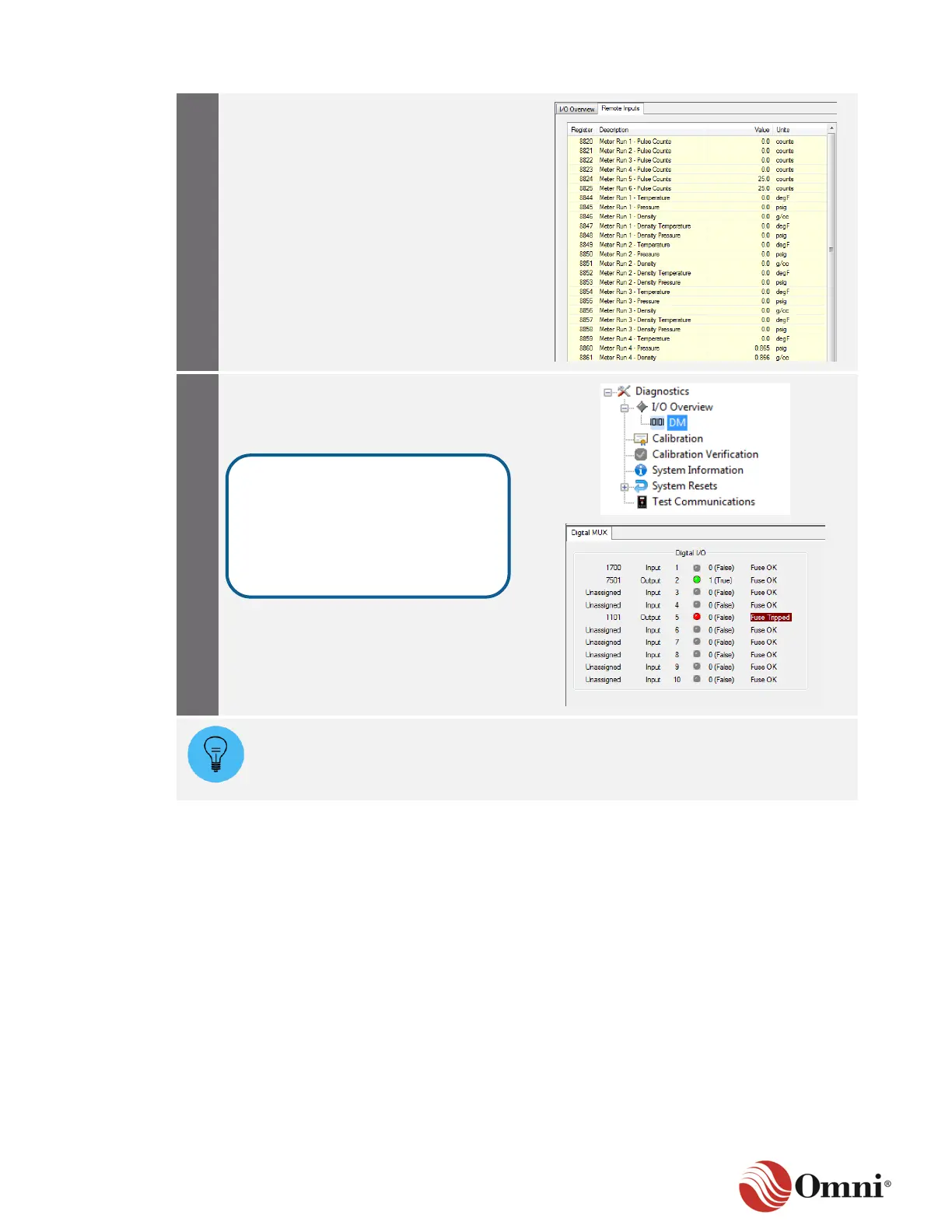
Click on the Remote Inputs tab to view a
list of live remote inputs coming from the
flow computer.
Click on DM in the Diagnostics tree. This
opens the Digital MUX screen, which
shows the digital I/O points for the modules
that are present in the system.
If an electronic fuse on the DM module has tripped, you should verify that the wiring
is correct between the external device and the flow computer (as depicted by your
installation drawings). If the wiring is correct, there may be a problem with the
external device.
7.2.2 Calibration
To calibrate an analog input channel, follow these instructions:
The Calibration menu can be accessed through the Diagnostics button on the Home ribbon. If
there is a project-specific requirement to reset all input and output channels before calibration,
perform the steps in the applicable Reset Single Channel Calibration or Reset Multiple Channel
Calibration instructions in Section 7.2.5 System Resets before calibrating.
The LED status indicators show
green (ON), gray (OFF or not in
use) or red when the fuse is
tripped. The far-right column
displays either “Fuse OK” or
“Fuse Tripped.”
 Loading...