88
CompoBus/S Distributed I/O Functions (SRM1 Only) Section 1-8
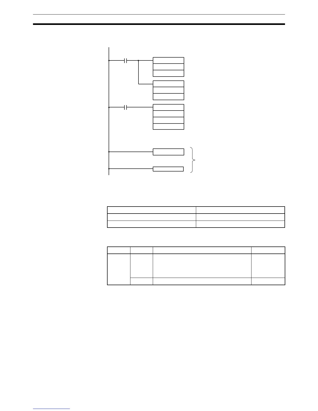
Application Example
(Scheduled Interrupt
Mode)
In this example, an interrupt is generated every 4.0 ms (1.0 ms × 4) after input
00005 goes ON; the interrupts execute interrupt subroutine number 23.
1-8 CompoBus/S Distributed I/O Functions (SRM1 Only)
No. of Connected Nodes A maximum of either 16 or 32 CompoBus/S nodes may be connected.
The maximum no. of nodes can be set from a Programming Device by making
the following settings in DM 6603.
Note When changes are made to these settings, always turn the power off and on
again to make the new setting effective.
Slave Interrupts Input bits in IR 000 to IR 007 and output bits in IR 010 to IR 017 are used as
interrupts for CompoBus/S I/O Terminals. The CompoBus/S I/O Terminal
interrupts (IN 0 to 15 and OUT 0 to 15) are allocated as indicated in the follow-
ing table.
IN0 to IN15 are the node addresses for the Input Terminals and OUT0 to
OUT15 are the node addresses for the Output Terminals.
RET(93)
MOV(21)
#0004
DM 0010
MOV(21)
#0010
DM 0011
SBN(92) 023
@STIM(69)
003
DM 0010
#0023
00005
25315 First Cycle Flag
ON for 1 cycle
Interrupt program
Sets the decrementing counter's set value to 4.
(BCD: 0000 to 9999)
Sets the decrementing time interval to 1.0 ms.
(BCD: 0005 to 0320)
Starts the interval timer in scheduled interrupt mode.
Specifies the first word containing the set value.
Specifies the subroutine number (only the lower by-
tes are effective).
No. of nodes set Communications response time
32 0.8 ms
16 0.5 ms
Word Bit(s) Function Setting
DM 6603 00 to 03 Sets the maximum no. of CompoBus/S nodes
to either 16 or 32.
00: 32 nodes
01: 16 nodes
00 or 01
04 to 15 Not used. 00

 Loading...


