225
Timer and Counter Instructions Section 5-15
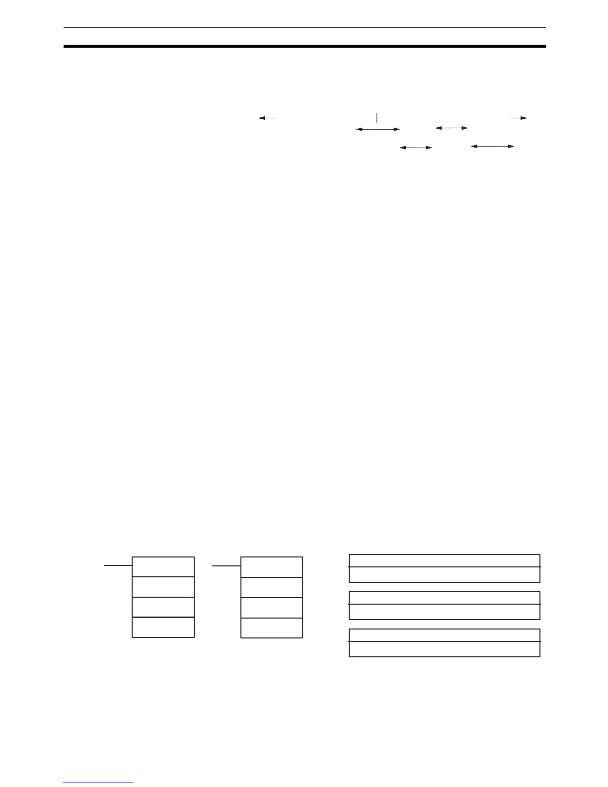
Range Comparison Operation
The following diagram illustrates the operation of range comparisons for range
settings 1 through 4 set consecutively in the comparison table.
As illustrated above, the current count is compared against all the comparison
ranges at the same time and the result for each range is output.
Flags ER: There is an error in the high-speed counter’s settings.
The specified port and function are not compatible.
There is a CTBL(63) instruction in the subroutine called by another
CTBL(63) instruction.
A CTBL(63) instruction using a different comparison format is execut-
ed during comparison.
Indirectly addressed DM word is non-existent. (Content of *DM word
is not BCD, or the DM area boundary has been exceeded.)
The comparison table exceeds the data area boundary, or there is an
error in the comparison table settings.
CTBL(63) is executed in an interrupt subroutine while a pulse I/O or
high-speed counter instruction is being executed in the main program.
AR 05: Flags AR 0500 to AR 0507 are turned ON to indicate when the PV of
high-speed counter 1 is in ranges 1 to 8.
AR 06: Flags AR 0600 to AR 0607 are turned ON to indicate when the PV of
high-speed counter 2 is in ranges 1 to 8.
AR 11 :Flags AR 1100 to AR 1107 are turned ON to indicate when the PV of
high-speed counter 0 is in ranges 1 to 8.
Subroutines are executed only once when the execution conditions are first
met. AR status is refreshed only once per cycle. If conditions are met for more
than one item in the table at the same time, the first item in the table takes pri-
ority.
5-15-7 MODE CONTROL – INI(61)
This instruction is not available for SRM1 PCs.
Limitations In the CPM1/CPM1A PCs, P must be 000 and C must be 000 to 003.
In CQM1 PCs, P must be 000, 001, or 002 and C must be 000 to 003.
P1 must be 000 unless C is 002.
Count
Range
1
0
Range
4
Range
3
Range
2
P: Port specifier
000, 001, or 002
Ladder Symbols
Operand Data Areas
@INI(61)
P
C
P1
P1: First PV word
IR, SR, AR, DM, HR, LR
C: Control data
000 to 003
INI(61)
P
C
P1

 Loading...


