345
Special Instructions Section 5-26
AR 0615: Port 2 output flag. ON when pulses are being output from port 2.
5-26-13PULSE WITH VARIABLE DUTY RATIO – PWM(––)
Limitations This instruction is available in the CQM1-CPU43-E/-EV1 only.
PWM(––) cannot be used unless the PC Setup (DM 6643 or DM 6644) is set
for variable duty ratio pulse outputs.
P must be 001 or 002 and F must be 000, 001, or 002.
D must be BCD between 0001 and 0099.
Description PWM(––) is used to output pulses with the specified duty ratio from port 1 or
2. The output can be set to one of three frequencies: 5.9 kHz, 1.5 kHz, or 91.6
Hz. The pulse output continues until INI(61) is executed to stop it.
In order for PWM(––) to be executed, the specified port must be set for vari-
able duty ratio pulse outputs in the PC Setup. Set the leftmost digit of
DM 6643 to 1 to enable variable duty ratio pulse output from port 1, and set
the leftmost digit of DM 6644 to 1 to enable variable duty ratio pulse output
from port 2. It is not possible to output normal pulses from a port that is set for
variable duty ratio output.
Note Refer to 1-3 Pulse Output Function (CQM1 Only) for more details.
Operand Settings P specifies the port where the pulses will be output. Pulses are output from
port 1 when P=001, and pulses are output from port 2 when P=002.
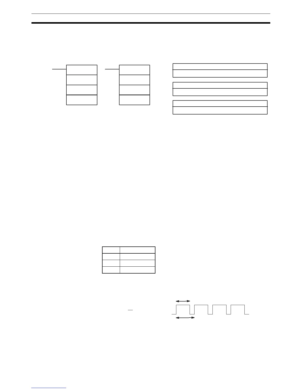
F specifies the frequency of the pulse output, as shown in the following table.
D specifies the duty ratio of the pulse output, i.e., the percentage of time that
the output is ON. D must be BCD from 0001 to 0099 (1% to 99%). The duty
ratio is 75% in the following diagram.
Flags ER: There is an error in the operand settings.
The CPU Unit is not a CQM1-CPU43-EV1.
The PC Setup is not set for variable duty ratio pulse output.
PWM(––) is executed in an interrupt subroutine while a pulse I/O or
high-speed counter instruction is being executed in the main program.
P: Communications port
001 or 002
Ladder Symbols Operand Data Areas
@PWM(––)
P
F
D
D: Duty ratio
IR, SR, AR, DM, HR, TC, LR, #
F: Frequency
000, 001, or 002
PWM(––)
P
F
D
F Frequency
000 5.9 kHz
001 1.5 kHz
002 91.6 Hz
T
t
on
= D (1% to 99%)
t
on
T