127
Advanced I/O Instructions (CQM1 Only) Section 2-2
2-2-4 7-SEGMENT DISPLAY OUTPUT – 7SEG(88)
This instruction outputs word data to a 7-segment display. It utilizes either 8
(for 4 digits) or 12 (for 8 digits) output bits.
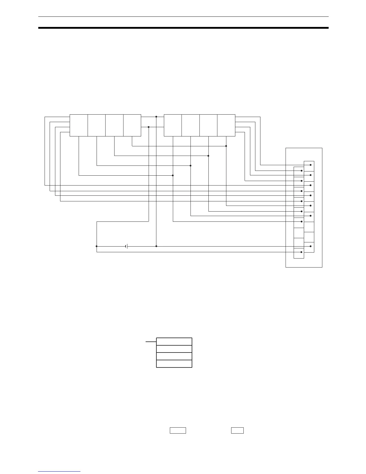
Hardware The 7-segment display is connected to an Output Unit as shown in the dia-
gram below. For 4-digit display, the data outputs (D0 to D3) are connected to
output points 0 through 3, and latch outputs (CS0 to CS3) are connected to
output points 4 through 7. Output point 12 (for 8-digit display) or output point 8
(for 4-digit display) will be turned ON when one round of data is displayed, but
there is no need to connect them unless required by the application.
The outputs can be connected from a Transistor Output Unit with 8 or more
output points for four digits or 16 or more output points for eight digits.
Note 1. Output Unit outputs normally employ negative logic. (Only the PNP output
type employs positive logic.)
2. The 7-segment display may require either positive or negative logic, de-
pending on the model.
Using the Instruction
If the first word holding the data to be displayed is specified at S, and the out-
put word is specified at O, and the SV taken from the table below is specified
at C, then operation will proceed as shown below when the program is exe-
cuted.
Data Storage Format
1
3
5
7
9
11
13
15
COM
0
2
4
6
8
10
12
14
DC
OD212
D
0
D
1
D
2
D
3
V
DD
(+)
V
SS
(0)
LE3 LE2 LE1 LE0
V
DD
(+)
V
SS
(0)
LE3 LE2 LE1 LE0
D
0
D
1
D
2
D
3
7SEG(88)
S
O
C
S: First source word
O: Output word
C: Control data
Leftmost 4 digits Rightmost 4 digits
S+1 S
 Loading...


