163
Basic Ladder Diagrams Section 4-3
If there is no END instruction anywhere in the program, the program will not
be executed at all.
Now you have all of the instructions required to write simple input-output pro-
grams. Before we finish with ladder diagram basic and go onto inputting the
program into the PC, let’s look at logic block instruction (AND LOAD and OR
LOAD), which are sometimes necessary even with simple diagrams.
4-3-6 Logic Block Instructions
Logic block instructions do not correspond to specific conditions on the ladder
diagram; rather, they describe relationships between logic blocks. The AND
LOAD instruction logically ANDs the execution conditions produced by two
logic blocks. The OR LOAD instruction logically ORs the execution conditions
produced by two logic blocks.
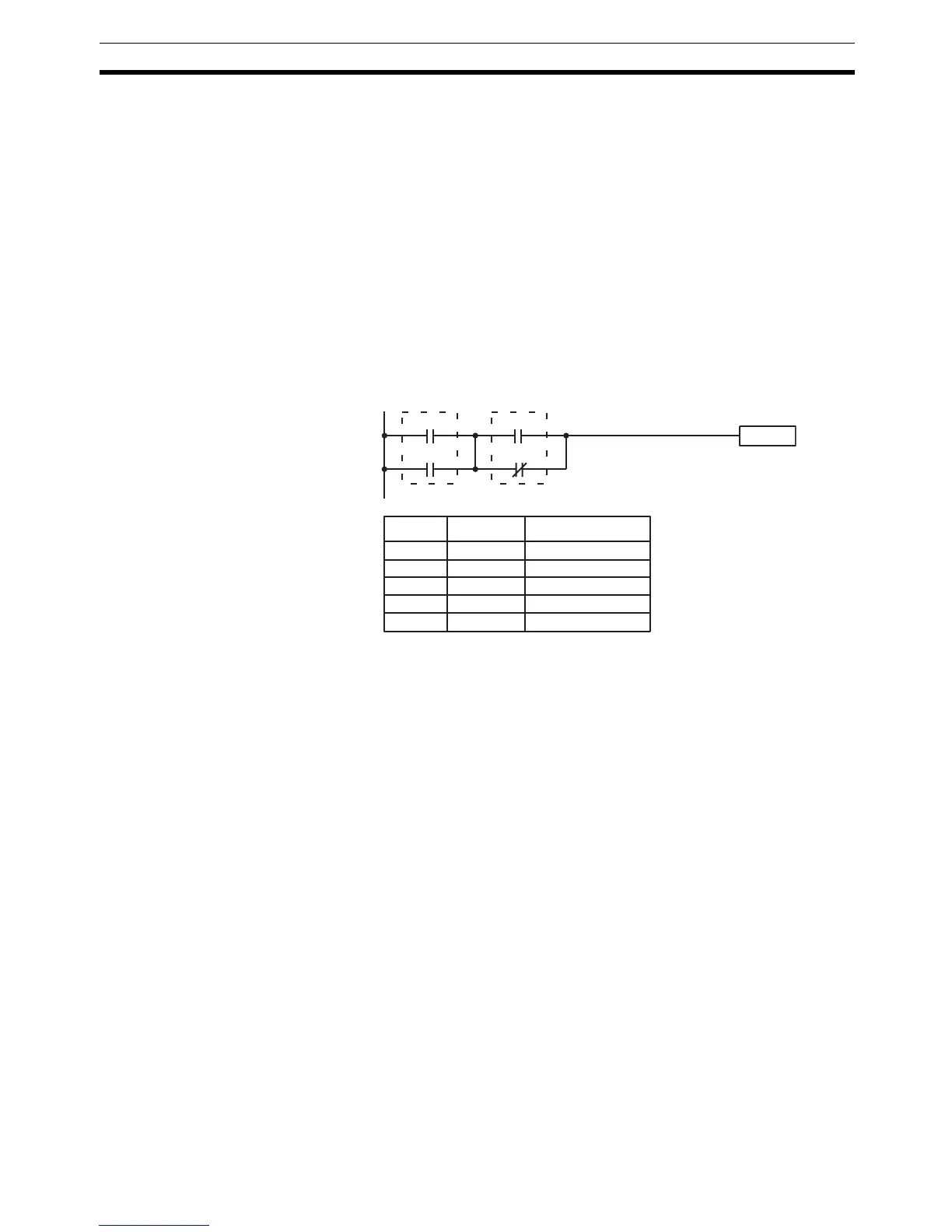
AND LOAD Although simple in appearance, the diagram below requires an AND LOAD
instruction.
The two logic blocks are indicated by dotted lines. Studying this example
shows that an ON execution condition will be produced when: either of the
conditions in the left logic block is ON (i.e., when either IR 00000 or IR 00001
is ON), and when either of the conditions in the right logic block is ON (i.e.,
when either IR 00002 is ON or IR 00003 is OFF).
The above ladder diagram cannot, however, be converted to mnemonic code
using AND and OR instructions alone. If an AND between IR 00002 and the
results of an OR between IR 00000 and IR 00001 is attempted, the OR NOT
between IR 00002 and IR 00003 is lost and the OR NOT ends up being an
OR NOT between just IR 00003 and the result of an AND between IR 00002
and the first OR. What we need is a way to do the OR (NOT)’s independently
and then combine the results.
To do this, we can use the LOAD or LOAD NOT instruction in the middle of an
instruction line. When LOAD or LOAD NOT is executed in this way, the current
execution condition is saved in special buffers and the logic process is begun
over. To combine the results of the current execution condition with that of a
previous “unused” execution condition, an AND LOAD or an OR LOAD
instruction is used. Here “LOAD” refers to loading the last unused execution
condition. An unused execution condition is produced by using the LOAD or
LOAD NOT instruction for any but the first condition on an instruction line.
Analyzing the above ladder diagram in terms of mnemonic instructions, the
condition for IR 00000 is a LOAD instruction and the condition below it is an
OR instruction between the status of IR 00000 and that of IR 00001. The con-
dition at IR 00002 is another LOAD instruction and the condition below is an
OR NOT instruction, i.e., an OR between the status of IR 00002 and the
inverse of the status of IR 00003. To arrive at the execution condition for the
Instruction
00002
00003
00000
00001
Address Instruction Operands
00000 LD 00000
00001 OR 00001
00002 LD 00002
00003 OR NOT 00003
00004 AND LD ---