47
CQM1 Interrupt Functions Section 1-5
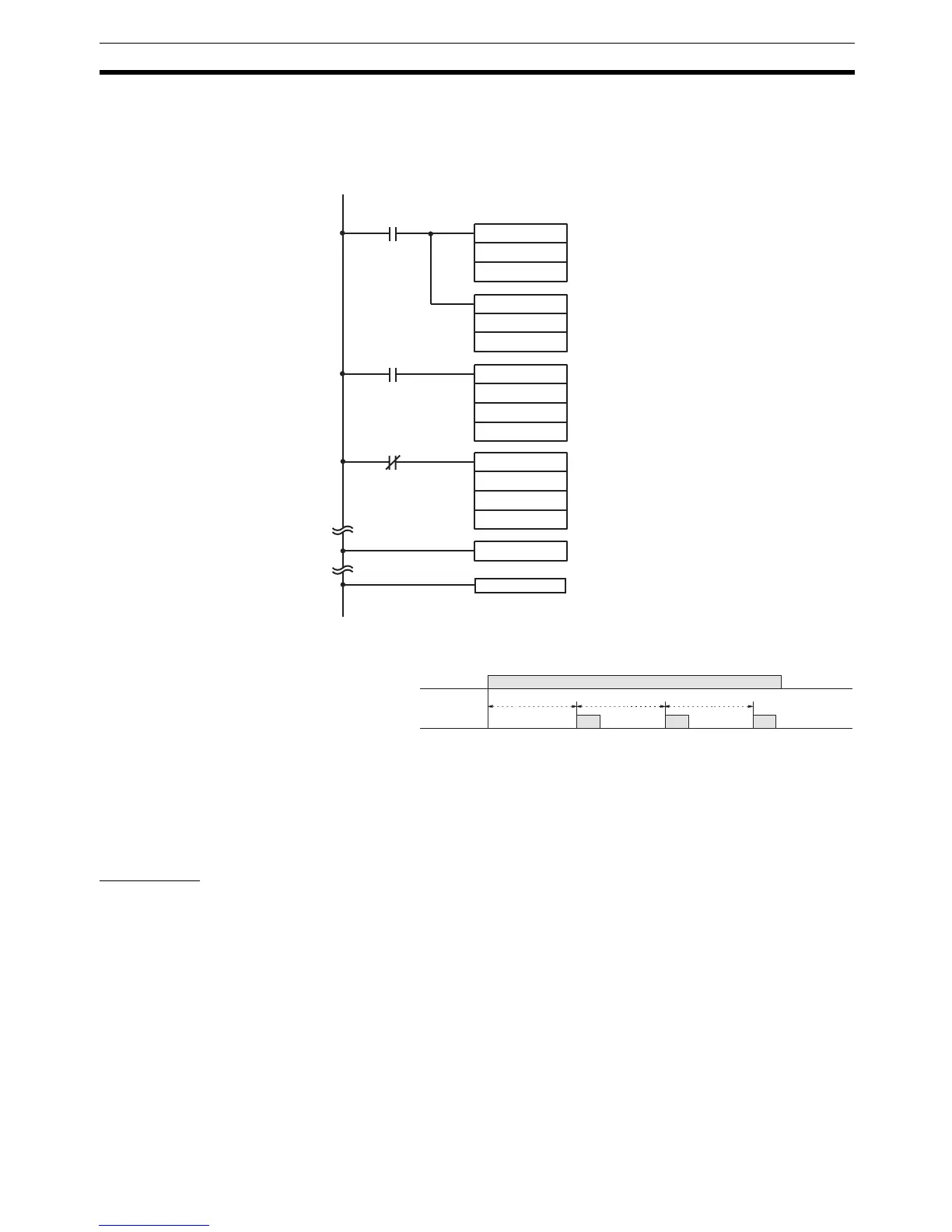
Application Example In this example, an interrupt is executed every 2.4 ms (0.6 ms x 4) by means
of interval timer 1. Assume the default settings for all of the PC Setup. (Inputs
are not refreshed for interrupt processing.)
When the program is executed, subroutine 023 will be executed every 2.4 ms
while IR 00100 is ON.
1-5-5 High-speed Counter 0 Interrupts
Pulse signals from a pulse encoder to CPU bits 00004 through 00006 can be
counted at high speed, and interrupt processing can be executed according to
the count.
Processing
Input Signal Types and
Count Modes
Two types of signals can be input from a pulse encoder. The count mode used
for high-speed counter 0 will depend on the signal type.
Up/Down Mode: A phase-difference 4X two-phase signal (A-phase and B-
phase) and a Z-phase signal are used for inputs. The
count is incremented or decremented according to differ-
ences in the 2-phase signals.
MOV(21)
#0004
DM 0010
MOV(21)
#0006
DM 0011
SBN(92) 023
@STIM(69)
004
DM 0010
#0023
@STIM(69)
011
000
000
00100
00100
Every 2.4 ms the count is reached for interval
timer 1, and subroutine 023 is called.
Interval timer set values:
Sets 4 for the decrementing counter
set value.
Sets 0.6 ms for the decrementing time inter-
val.
Interval timer 1 starts when IR 00100 turns ON.
Interval timer 1 stops when IR 00100 turns
OFF.
25315 First Cycle Flag
ON for 1 cycle
RET(93)
IR 00100
Subroutine 023
2.4 ms 2.4 ms 2.4 ms