350
Communications Instructions Section 5-27
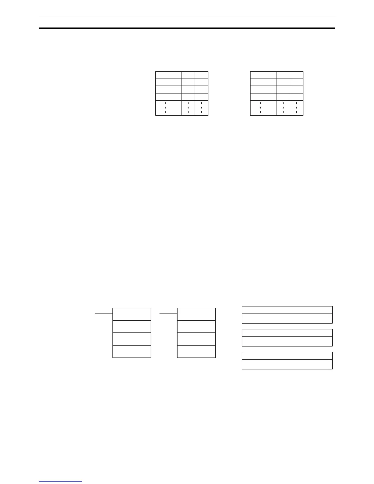
The order in which data is written to memory depends on the value of digit 0
of C. Eight bytes of data 12345678... will be written in the following manner:
Flags ER: The CPU Unit is not equipped with an RS-232C port.
Another device is not connected to the specified port.
There is an error in the communications settings (PC Setup) or the op-
erand settings.
Indirectly addressed DM word is non-existent. (Content of *DM word
is not BCD, or the DM area boundary has been exceeded.)
The destination words (D to D+(N
÷2)–1) exceed the data area.
AR 08: AR 0806 will be turned ON when data has been received normally at
the RS-232C port. Reset when RXD(47) is executed.
AR 0814 will be turned ON when data has been received normally at
the peripheral port. Reset when RXD(47) is executed.
AR 09: Contains the number of bytes received at the RS-232C port. Reset to
0000 when RXD(47) is executed.
AR 10: Contains the number of bytes received at the peripheral port. Reset to
0000 when RXD(47) is executed.
Note Communications flags and counters can be cleared either by specifying 0000
for N or using the Port Reset Bits (SR 25208 for peripheral port and SR 25209
for RS-232C port.)
5-27-2 TRANSMIT – TXD(48)
Limitations This instruction is available in the CQM1/SRM1 only.
S and S+(N÷2)–1 must be in the same data area.
DM 6144 to DM 6655 cannot be used for S or N.
N must be BCD from #0000 to #0256. (#0000 to #0061 in host link mode)
Description When the execution condition is OFF, TXD(48) is not executed. When the exe-
cution condition is ON, TXD(48) reads N bytes of data from words S to
S+(N
÷2)–1, converts it to ASCII, and outputs the data from the specified port.
MSB LSB
D12
D+1 3 4
D+2 5 6
D+3 7 8
Digit 0 = 0
MSB LSB
D21
D+1 4 3
D+2 6 5
D+3 8 7
Digit 0 = 1
S: First source word
IR, SR, AR, DM, HR, TC, LR
C: Control word
#
Ladder Symbols
Operand Data Areas
N: Number of bytes
IR, SR, AR, DM, HR, TC, LR, #
TXD(48)
S
C
N
@TXD(48)
S
C
N