105
Communications Functions Section 1-9
4. If an out-of-range value is set, the following communications conditions will
result. In that case, reset the value so that it is within the permissible range.
Communications mode: Host Link
Communications format: Standard settings
(1 start bit, 7-bit data; even parity, 2 stop bits,
9,600 bps)
Transmission delay: No
Node number: 00
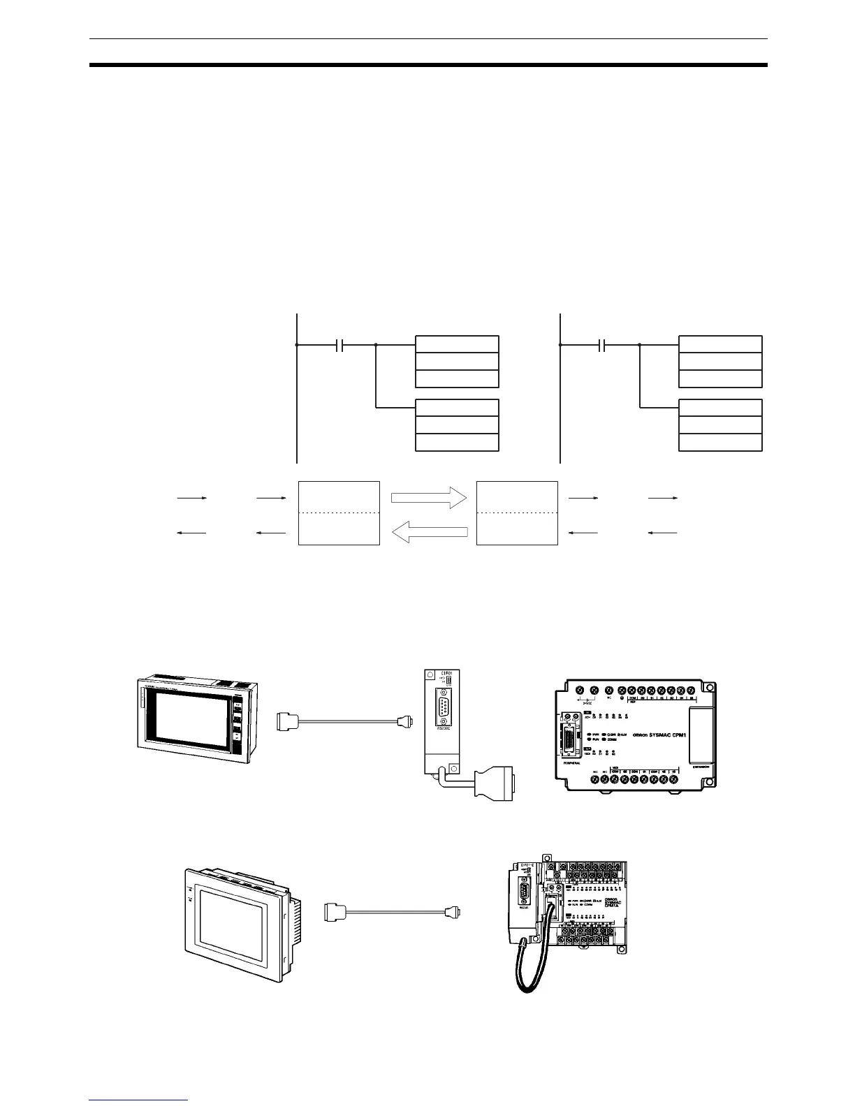
Example Program This example shows ladder programs that copy the status of IR 000 in each
CPM1/CPM1A to SR 200 in the other CPM1/CPM1A.
1-9-9 CPM1/CPM1A NT Link Communications
Using the NT link, the CPM1/CPM1A PC can connected to the Programmable
Terminal (NT Link Interface) through an RS-232C Adapter.
CPM1 PCs
CPM1A PCs
25313 (Always ON)
MOV(21)
000
LR00
MOV(21)
LR08
200
Program in the Master
MOV(21)
000
LR08
MOV(21)
LR00
200
25313 (Always ON)
Program in the Slave
LR00
LR07
LR08
LR00
LR07
LR08
LR15
Writing area
Reading area
Write
Read
Reading area
Writing area
LR15
Write
Read
IR 000
SR 200
IR 000
SR 200
CPM1 CPU UnitRS-232C Adapter
Programmable Terminal
RS-232C Cable
CPM1 CPU
OMRON Programmable Terminal
RS-232C Cable
CPM1A CPU Unit
RS-232C
Adapter
 Loading...


