202
Bit Control Instructions Section 5-8
OUT turns ON the designated bit for an ON execution condition, and turns
OFF the designated bit for an OFF execution condition. With a TR bit, OUT
appears at a branching point rather than at the end of an instruction line.
Refer to 4-3-8 Branching Instruction Lines for details.
OUT NOT turns ON the designated bit for a OFF execution condition, and
turns OFF the designated bit for an ON execution condition.
OUT and OUT NOT can be used to control execution by turning ON and OFF
bits that are assigned to conditions on the ladder diagram, thus determining
execution conditions for other instructions. This is particularly helpful and
allows a complex set of conditions to be used to control the status of a single
work bit, and then that work bit can be used to control other instructions.
The length of time that a bit is ON or OFF can be controlled by combining the
OUT or OUT NOT with TIM. Refer to Examples under 5-15-1 TIMER – TIM for
details.
Flags There are no flags affected by these instructions.
5-8-2 SET and RESET – SET and RSET
Description SET turns the operand bit ON when the execution condition is ON, and does
not affect the status of the operand bit when the execution condition is OFF.
RSET turns the operand bit OFF when the execution condition is ON, and
does not affect the status of the operand bit when the execution condition is
OFF.
The operation of SET differs from that of OUT because the OUT instruction
turns the operand bit OFF when its execution condition is OFF. Likewise,
RSET differs from OUT NOT because OUT NOT turns the operand bit ON
when its execution condition is OFF.
Precautions The status of operand bits for SET and RSET programmed between IL(02)
and ILC(03) or JMP(04) and JME(05) will not change when the interlock or
jump condition is met (i.e., when IL(02) or JMP(04) is executed with an OFF
execution condition).
Flags There are no flags affected by these instructions.
Examples The following examples demonstrate the difference between OUT and SET/
RSET. In the first example (Diagram A), IR 10000 will be turned ON or OFF
whenever IR 00000 goes ON or OFF.
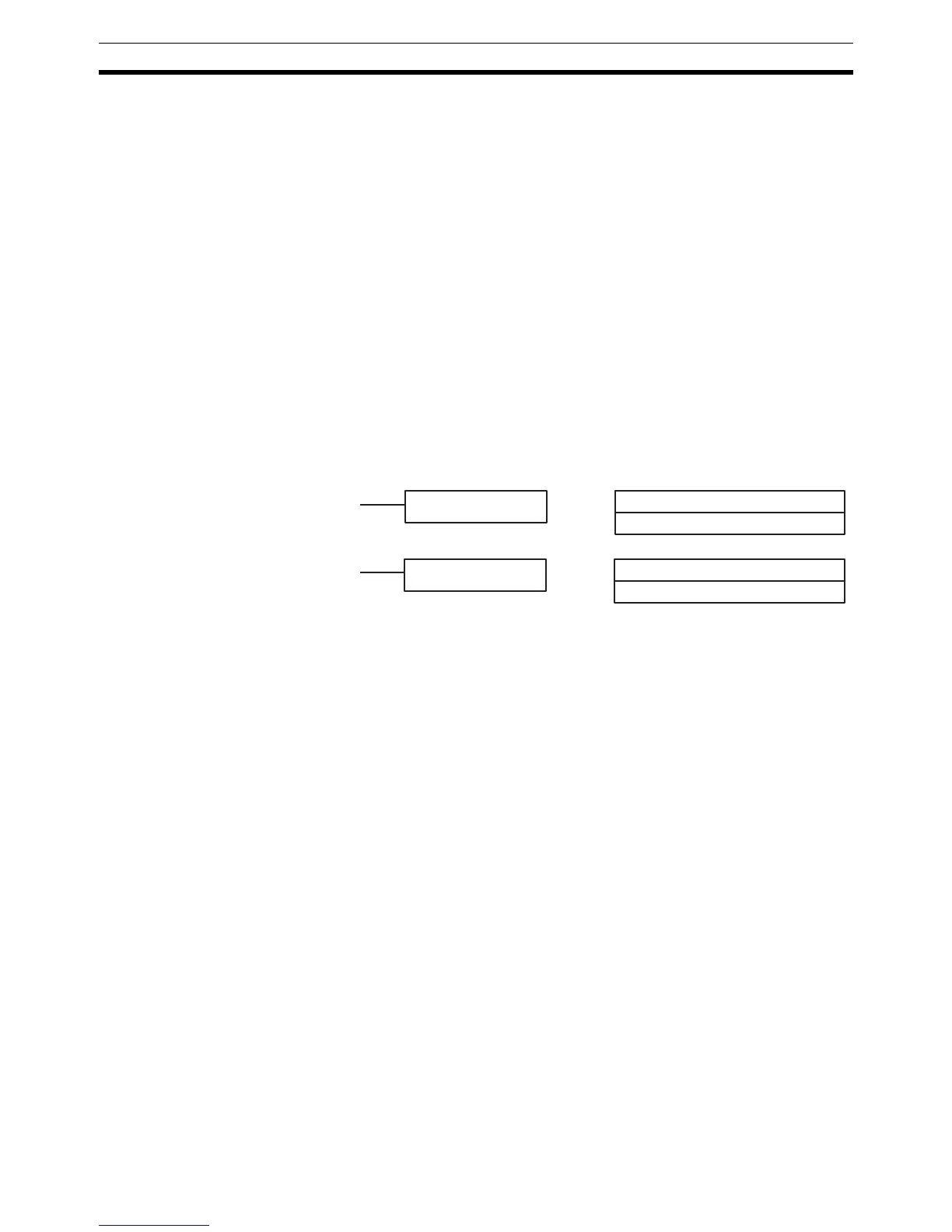
B: Bit
IR, SR, AR, HR, LR
Ladder Symbols Operand Data Areas
SET B
B: Bit
IR, SR, AR, HR, LR
RSET B