157
Basic Ladder Diagrams Section 4-3
location is also designated as an operand. A bit whose address is designated
as an operand is called an operand bit; a word whose address is designated
as an operand is called an operand word. If the actual value is entered as a
constant, it is preceded by # to indicate that it is not an address.
Other terms used in describing instructions are introduced in SECTION 5
Instruction Set.
4-3 Basic Ladder Diagrams
A ladder diagram consists of one line running down the left side with lines
branching off to the right. The line on the left is called the bus bar; the branch-
ing lines, instruction lines or rungs. Along the instruction lines are placed con-
ditions that lead to other instructions on the right side. The logical
combinations of these conditions determine when and how the instructions at
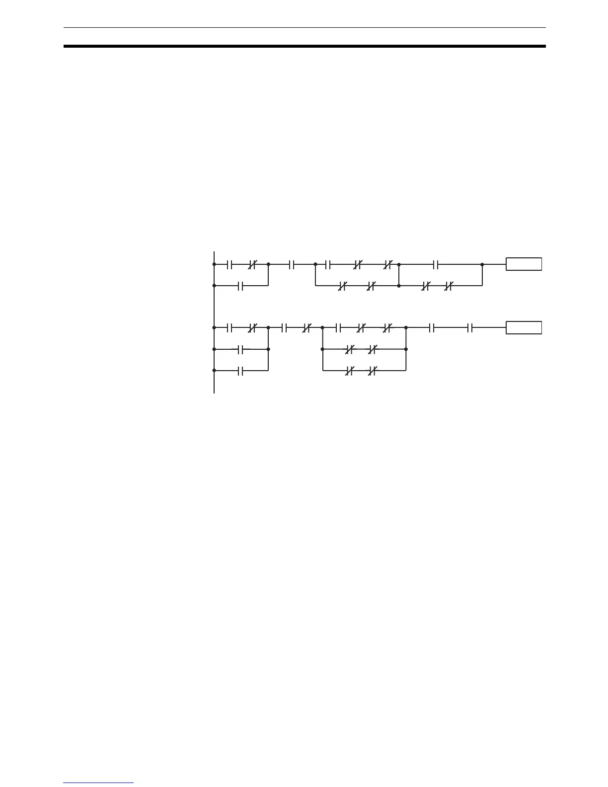
the right are executed. A ladder diagram is shown below.
As shown in the diagram above, instruction lines can branch apart and they
can join back together. The vertical pairs of lines are called conditions. Condi-
tions without diagonal lines through them are called normally open conditions
and correspond to a LOAD, AND, or OR instruction. The conditions with diag-
onal lines through them are called normally closed conditions and correspond
to a LOAD NOT, AND NOT, or OR NOT instruction. The number above each
condition indicates the operand bit for the instruction. It is the status of the bit
associated with each condition that determines the execution condition for fol-
lowing instructions. The way the operation of each of the instructions corre-
sponds to a condition is described below. Before we consider these, however,
there are some basic terms that must be explained.
Note When displaying ladder diagrams with the SSS, a second bus bar will be
shown on the right side of the ladder diagram and will be connected to all
instructions on the right side. This does not change the ladder-diagram pro-
gram in any functional sense. No conditions can be placed between the
instructions on the right side and the right bus bar, i.e., all instructions on the
right must be connected directly to the right bus bar. Refer to the SSS Opera-
tion Manual: C-series PCs for details.
4-3-1 Basic Terms
Normally Open and
Normally Closed
Conditions
Each condition in a ladder diagram is either ON or OFF depending on the sta-
tus of the operand bit that has been assigned to it. A normally open condition
is ON if the operand bit is ON; OFF if the operand bit is OFF. A normally
closed condition is ON if the operand bit is OFF; OFF if the operand bit is ON.
Generally speaking, you use a normally open condition when you want some-
00000 06315
Instruction
Instruction
00403
00001
HR 0109 LR 250325208 24400
00501 00502 00503 00504
24401
00100 00002
00010
00011
00003 HR 0050 00007 TIM 001 LR 0515
21001 21002
00405
21005 21007