201
Bit Control Instructions Section 5-8
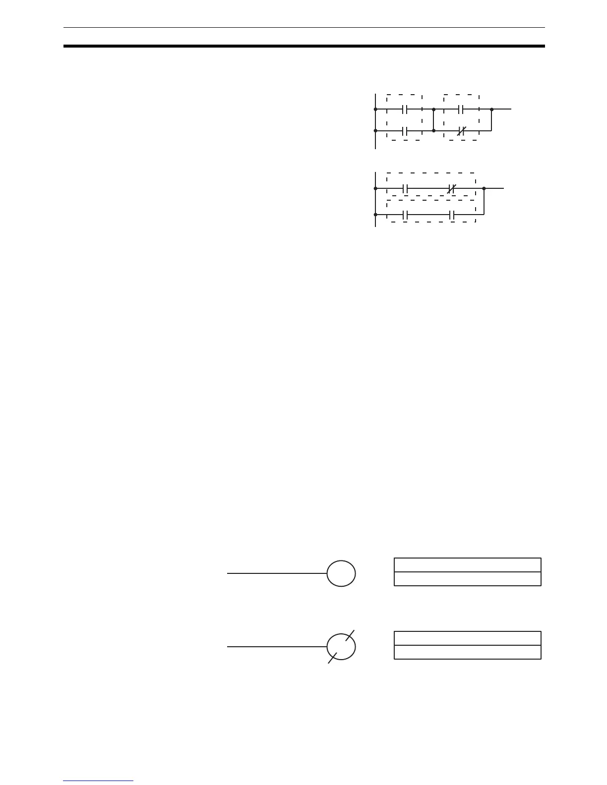
5-7-2 AND LOAD and OR LOAD
Description When instructions are combined into blocks that cannot be logically combined
using only OR and AND operations, AND LD and OR LD are used. Whereas
AND and OR operations logically combine a bit status and an execution con-
dition, AND LD and OR LD logically combine two execution conditions, the
current one and the last unused one.
In order to draw ladder diagrams, it is not necessary to use AND LD and OR
LD instructions, nor are they necessary when inputting ladder diagrams
directly, as is possible from the SSS. They are required, however, to convert
the program to and input it in mnemonic form.
In order to reduce the number of programming instructions required, a basic
understanding of logic block instructions is required. For an introduction to
logic blocks, refer to 4-3-6 Logic Block Instructions.
Flags There are no flags affected by these instructions.
5-8 Bit Control Instructions
There are seven instructions that can be used generally to control individual
bit status. These are OUT, OUT NOT, DIFU(13), DIFD(14), SET, RSET, and
KEEP(11). These instructions are used to turn bits ON and OFF in different
ways.
5-8-1 OUTPUT and OUTPUT NOT – OUT and OUT NOT
Limitations Any output bit can generally be used in only one instruction that controls its
status.
Description OUT and OUT NOT are used to control the status of the designated bit
according to the execution condition.
Ladder Symbol
AND LOAD – AND LD
00002
00003
00000
00001
Ladder Symbol
OR LOAD – OR LD
00000 00001
00002 00003
B: Bit
IR, SR, AR, HR, LR, TR
Ladder Symbol Operand Data Areas
OUTPUT – OUT
B
B: Bit
IR, SR, AR, HR, LR
Ladder Symbol Operand Data Areas
OUTPUT NOT – OUT NOT
B

 Loading...


