129
Advanced I/O Instructions (CQM1 Only) Section 2-2
The 8-digit BCD data in DM 0120 (rightmost 4 digits) and DM 0121 (leftmost 4
digits) are always displayed by means of 7SEG(88). When the contents of
DM 0120 and DM 0121 change, the display will also change.
2-2-5 Alternate I/O Bits
Although the advanced I/O instructions generally using I/O bits starting from
bit 00 of the specified words, they can be programmed through intermediate
words to use other I/O bits. The following example shows how this can be
achieved for HKY(––).
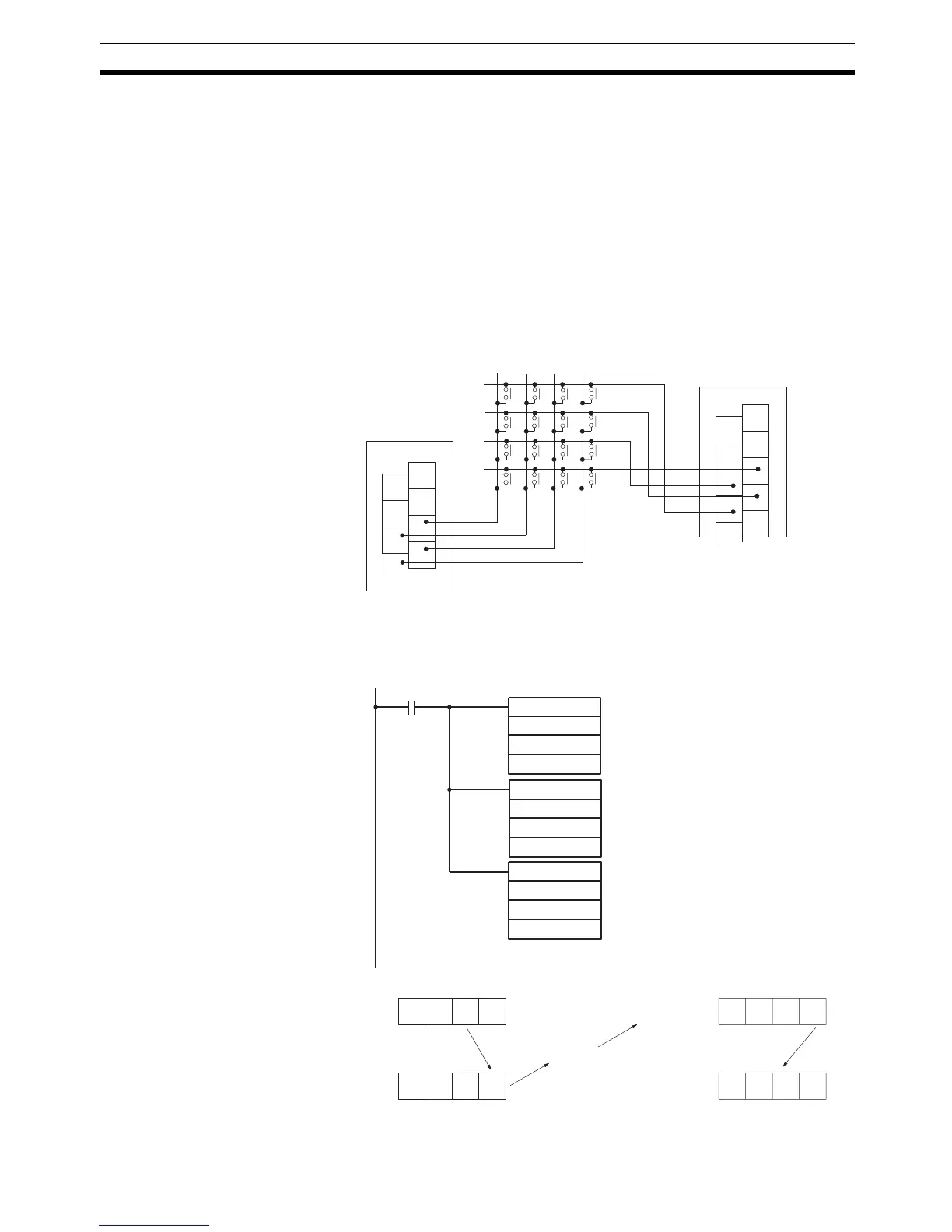
Example The following wiring and program examples show how to use input bits
IR 00004 through IR 00007 and output bits IR 10004 through IR 10007 to
input values from a hexadecimal keypad.
Wiring Diagram (Not Complete)
Program
1
3
5
7
0
2
4
6
ID212
1
3
5
7
9
0
2
4
6
8
OD212
C
8
4
0
D
9
5
1
E
A
6
2
F
B
3
7
Input terminals
IR 000
Output Unit
IR 100
Note Power su
lines have been omitted.
HKY
DM0000
DM0100
DM1000
MOVD (83)
DM0100
#0100
100
MOVD(83)
000
#0001
DM0000
25313 (Always ON)
Bits 04 through 07 of IR 000 are
transferred to bits 00 through 03 of DM
0000.
HKY execution
DM 0100
015015
IR 000
DM 0000
IR 100
Input
Output
HKY is coded using DM 0000 as the
input word and DM 0100 as the output
word. Execution results are placed in
DM 1000 to DM 1002.
Bits 00 through 03 of DM 0100 are
transferred to bits 04 through 07 of IR
100.

 Loading...


