5.21
Final Drive/Brake System
5
Overview
The Polaris snowmobile hydraulic brake system consists
of the following components or assemblies: brake lever,
master cylinder, hydraulic hose, brake caliper (slave
cylinder), brake pads, and a brake disc which is secured
to the drive line.
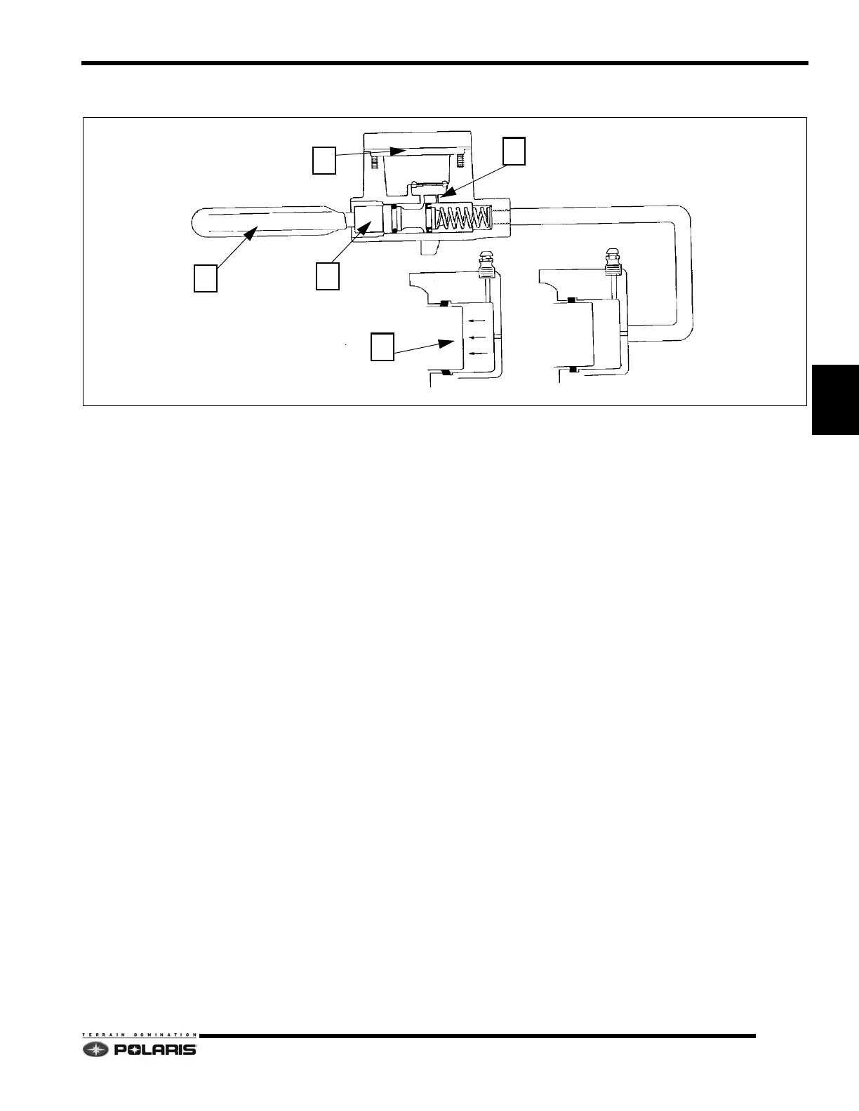
When the hand activated brake lever (A) is applied, it
co
ntacts a piston (B) within the master cylinder. As the
master cylinder piston moves inward it closes a small
opening called a compensating port (C) within the cylinder
and starts to build pressure within the brake system. As
the pressure within the system is increased, the pistons
(D) located in the brake caliper move toward the disc and
applies pressure to the moveable brake pads. As the lever
pressure is increased, the braking effect is increased.
The friction applied to the brake pads will cause the pads
to wear
. As the pads wear, the piston within the caliper self-
adjusts and moves further outward.
Brake fluid level is critical to p
roper system operation. A
low fluid level allows air to enter the system causing the
brakes to feel spongy.
Compensating Port
Located within the master cylinder is a small
compensating port (C) which is opened and closed by the
master cylinder piston assembly. The port is open when
the brake lever is released and the piston is outward. As
the temperature within the hydraulic system changes, this
port compensates for fluid expansion caused by heat, or
contraction caused by cooling. During system service, be
sure this port is open. Due to the high temperatures
created within the system during heavy braking, it is very
important that the master cylinder reservoir have
adequate space to allow for the brake fluid to expand.
Master cylinder reservoirs should be filled to the top of the
fluid level mark on the inside of the reservoir, 1/4” - 5/16”
(.6 -.8 cm) below lip of reservoir opening.
This system also incorporates a diaphragm (E) as part of
th
e cover gasket and a vent port (on cover) located
between the gasket and the cover. The combination
diaphragm and vent allow for the air above the fluid to
equalize pressure as the fluid expands or contracts. Be
sure the vent is open and allowed to function. If the
reservoir is overfilled or the diaphragm vent is plugged, the
expanding fluid may build pressure in the brake system
and lead to brake failure.

 Loading...


