10.30
Battery and Electrical Systems
Combination AC/DC Regulator - Battery
Charge Rectifier
2013 DC-CFI models feature a combination AC/DC
regulator with battery charge rectifier. The module
regulates all AC and DC power for the vehicle and
rectifies power for all DC circuits and for charging the
battery.
The combination AC/DC regulator is mounted to the
clutch co
ver with the cooling fins exposed to the drive
clutch.
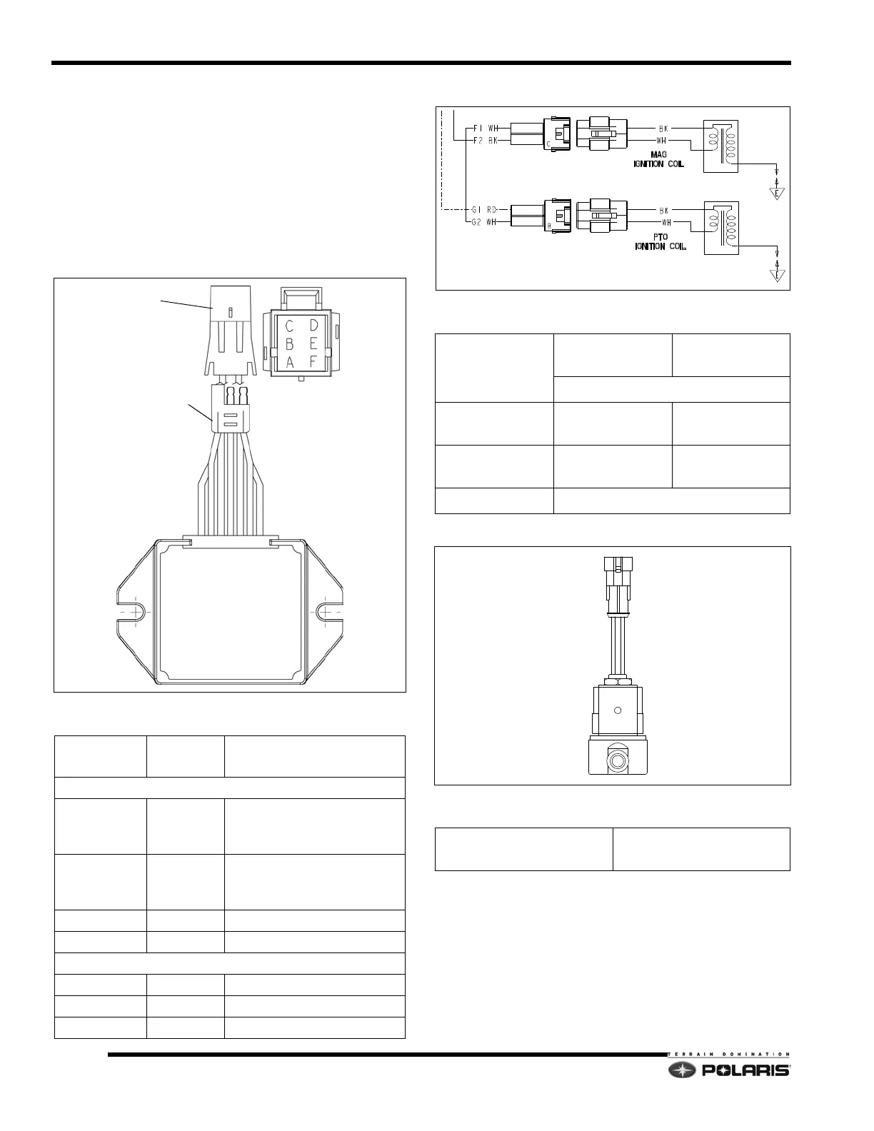
Ignition Coil Packs
Exhaust Valve Solenoid
DC-CFI Combination Regulator Connections
CONNECTOR
WIRE
COLORS
ITEM
6 PIN Connector - CFI System Power
A - Chassis RED
14.5 VDC Chassis power.
(Instrument cluster/EV
s
olenoid/DC power points)
B/E - Boost ORANGE
VDC supplied to ECU to
bo
ost power to fuel pump
during engine start-up.
C/D - Stator YELLOW VAC from stator coils.
F - Ground BROWN Ground
3 PIN Connector - Regulated AC / DC Battery Charge
1 - Ground BROWN Ground
2 - AC PWR YELLOW 14.3 Regulated AC PWR
3 - DC PWR RED 14.7 DC PWR (Battery)
3 PIN AC/BATTERY
6 PIN CHASSIS
Specifications
Coil Pack
Wires/Leads
600 DC-CFI-4
600/800
DC
-CFI-2
+/- 15% @ 68°F (20°C)
BLACK to WHITE
(Pr
imary)
0.20 0.45
BLACK to
Secondary Lead
6.3K 18K
Plug cap 5K
Specifications
Coil Resistance
(WH/YE to RED)
15 +
/- 15% @ 68°F (20°C)

 Loading...


