2.6
Maintenance
BREAK-IN PROCEDURES
Engine Break-In Procedure
The first tank of fuel is considered the break-in period for
the engine. During this time it is critical to not operate the
engine at full throttle for more than a few seconds. Vary the
throttle speed as much as possible. Monitor engine
temperatures and fluid levels often during the break-in
period.
NOTE: During the engine break-in period, verify the
oil inject
ion system is functioning by monitoring the
oil level in the oil tank. If the oil level does not drop,
inspect the oil injection system.
Polaris recommends filling the oil t
ank and pre-mixing the
first full tank of fuel with Premium 2-Cycle Semi-Synthetic
Oil when the engine is either new or refurbished (new
pistons, crankshaft, cylinder, etc.). Polaris semi-synthetic
engine oil will seat the rings faster than when using Polaris
VES Gold Plus oil.
After the break-in period use Polaris VES Gold P
lus
engine oil for normal operation.
Fuel/Oil Premix Ratio
During the break-in period, premix the first tank a fuel (10
US gallons) using a 40:1 (fuel:oil) ratio.
Formula = 1 US Gallon = 128 oz. / 40 (Desired Ratio) =
3
.2 oz. for every 1 US gallon of fuel.
10 US gallons of fuel require 32 oz. of oil to achieve a 40:1
p
remix ratio.
Always mix fuel and oil 5 gallons at a time. Never fill the
t
ank with fuel and then add oil.
Drive Belt Break-In Procedure
The break-in period for a new drive belt is 30 miles. During
this time, vary the throttle position under 50% and limit full
throttle use.
New drive belts that feature a sanded finish should be first
washed with
warm, soapy water and allowed to air dry
prior to use.
Always take time to warm up the
belt and driveline prior to
operating the snowmobile. Free track and skis from the
ground before engaging throttle.
ENGINE MAINTENANCE
Variable Exhaust Valve Cleaning
The exhaust valve guillotines must be cleaned to ensure
maximum engine performance and throttle response.
1. Remove the vent hose f
rom the EV base fitting.
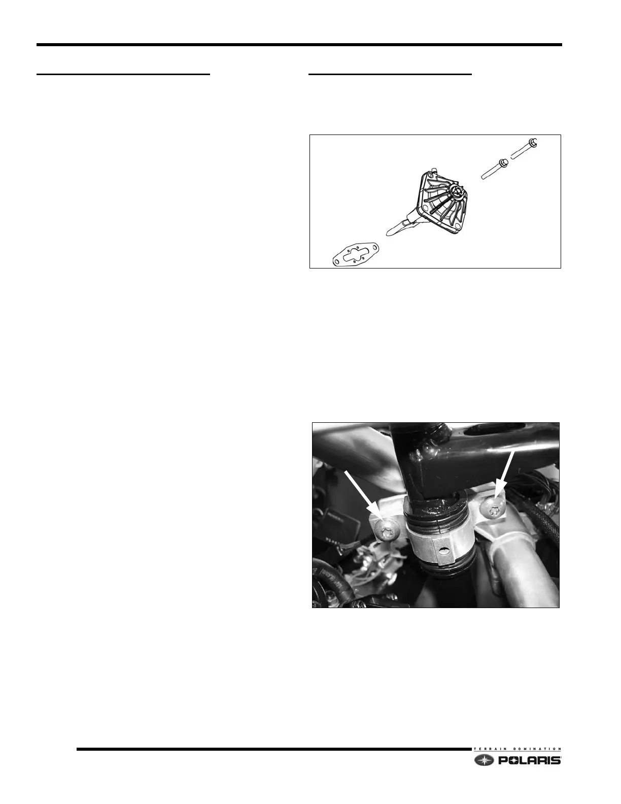
2. On the MAG VES assembly, remove the two
fa
steners that secure the valve assembly to the
cylinder. Remove the cover after the assembly is
removed from the engine.
3. On the PTO VES assembly, remove all four screws.
Re
move the cover and spring from the EV base.
4. Remove the two screws that secure the lower steering
s
haft clamp to the over structure. Doing this will
provide clearance to remove the EV valve assembly.
5. Carefully extract the guillotine out of the cylinder.
Discar
d the gasket. Do not excessively push on the
lower steering shaft when removing the EV assembly.
6. Using a clean rag or shop towel, remove the oil
residue from the c
ylinder, guillotine, and EV base.
GASKET
EV ASSEMBLY
FASTENERS
GUILLOTINE

 Loading...


