6.25
PVT System
6
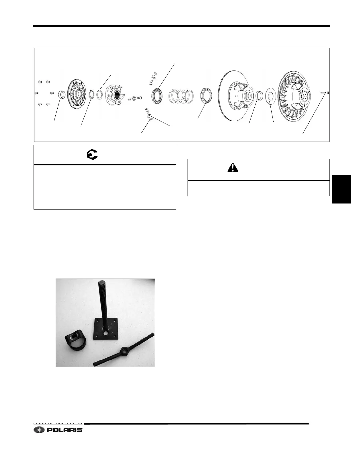
Polaris SPA-P2 Driven Clutch Components
Disassembly and Assembly Process
1. Remove the driven cover screws and cover. Note the
“
X” in the cover and moveable sheave are in
alignment.
2. Install the clutch into a s
crew-down clutch
compression fixture. Screw-down clutch compressors
are commercially available through after-market
companies such as Team Industries Inc.
NOTE: The 8700220 clutch compressor and PS-45909
e
xtensions will not work on a P2 driven clutch.
3. Remove the snap ring. Verify the washer is not lodged
in
side the snap ring groove.
4. Unscrew the compressor to remov
e the helix, spring
cups and spring. Note the orientation of the spring
spacer, spring cup, and tabbed spring. Disassemble
the clutch sheaves.
5. Inspect the helix, cup/spacer, spring, bushings,
r
ollers, and clutch sheaves for damage.
6. The cover and sheave bushings are not serviceable.
If bush
ings are severely worn or binding, clutch
assembly replacement is required.
7. Clean the sheaves with a Scotch Brite pad and a
solution of
warm, soapy water.
8. Inspect the rollers for abnormal wear and replace as
re
quired. Install new rollers with the ejector pin marks
on the rollers facing center of sheave (visible).
9. Install the sheave spacer, and then the moveable
sh
eave.
10. Next, install the metal spring cup, spring, and then
sp
ring spacer. Make sure the spring tab is in one of
the spring cup holes, and engaged in the moveable
sheave hole.
11. Slide the helix down the stationary shaft.
DRIVEN COVER
RETAINING RING
WASHER
HELIX
SPRING w/TAB
WASHER
ROLLER
MOVEABLE SHEAVE
BUSHING
BUSHING
SPACER
STATIONARY SHEAVE
ADJUSTER SCREW / LOCK NUT
SPRING CUP w/TAB HOLES
(NO SERVICE)
(NO SERVICE)
SPACER
Driven Cover Screws: 12 ft-lbs (16Nm)
Deflection Adjuster Screw Lock Nut: 10 ft-lbs
(12Nm)
Driven Clutch Retaining Fastener: 18 ft-lbs (25 Nm)
Roller Fasteners: 110 in-lbs (12.5 Nm)
Driven spring under pressure. Wear eye protection
when removing snap ring and helix.

 Loading...


