10.31
Battery and Electrical Systems
10
Oil Level Sender
To test the oil level sender, position the sender as it would
be in the oil tank. Allow the float to drop in the direction it
would if the oil tank were empty. Continuity should be
present when using a multimeter to test the sender with
the float in the “empty” position.
No continuity should be present when the float is moved
aw
ay from the “empty” position.
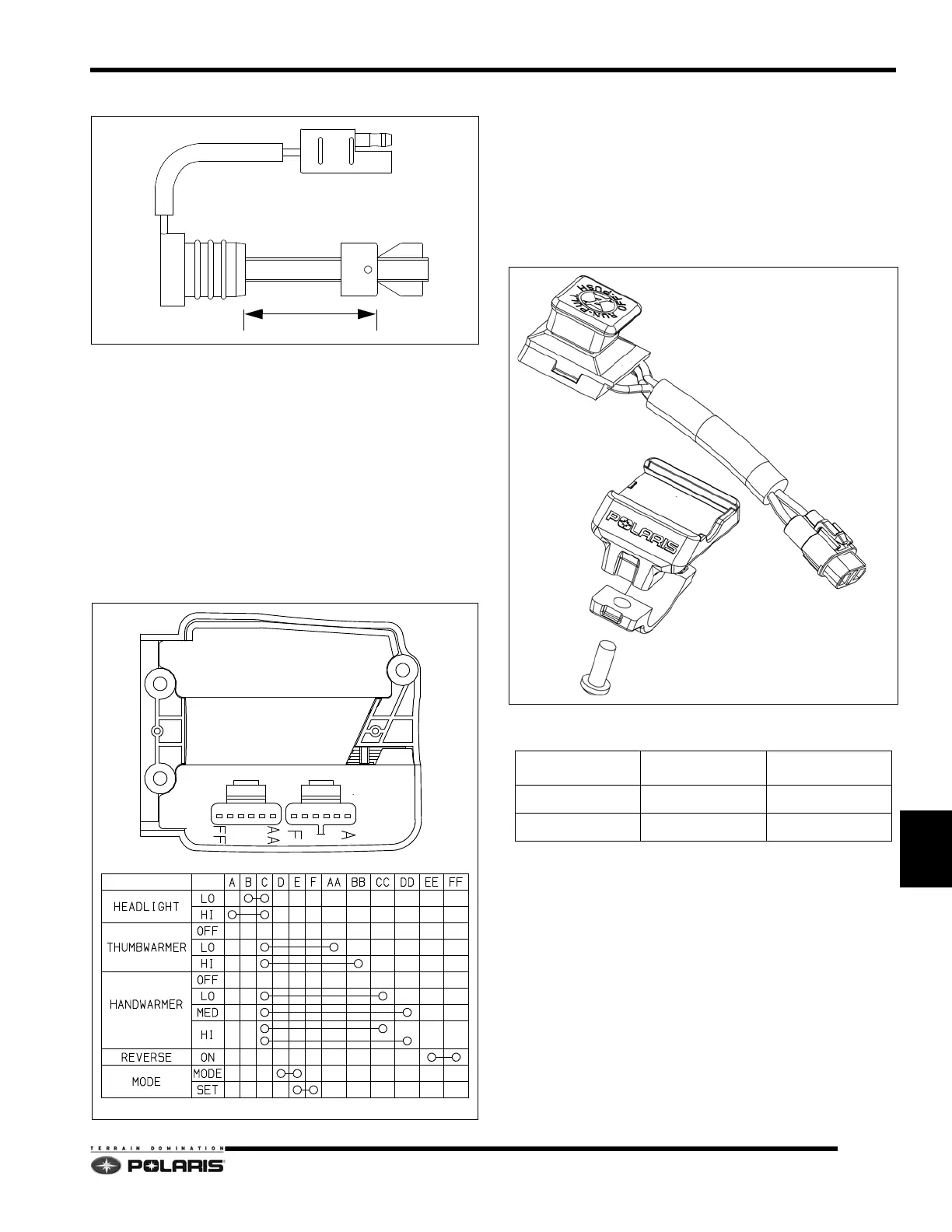
LH Control Assembly
Test the left hand (LH) control assembly using a
multimeter set to show continuity. Reference the
illustration below for continuity checks.
Auxiliary Stop Switch
The auxiliary stop switch is a hard stop switch and will
shut off the engine when pushed down.
There are two switch types used on PRO-RIDE
snowmo
biles, but both types function the same. Type one
switches are integrated into the right hand throttle block.
Type two switches are snapped into a bracket which is
secured directly to the handlebar tube.
Stop Switch Continuity
BK/BLU BLK
UP
DOWN X X
TYPE 2 SWITCH
STOP SWITCH
BRACKET

 Loading...


