6.15
PVT System
6
PVT SYSTEM ADJUSTMENTS
Clutch Alignment/Offset
The drive and driven clutches are offset from each other.
This offset is controlled by the number and thickness of
washers installed on the jackshaft behind the driven
clutch.
1. Remove drive belt.
2. Push the driven clutch towards the bulkhead. Install
the
alignment tool into the drive clutch and on top of
the driven clutch hub.
NOTE: The PS-47477 offset tool is calibrated with the
c
orrect alignment angle for the respective driven
clutch.
Inspect for broken motor mounts, engine straps or
bu
lkhead damage if the offset tool reveals major mis-
alignment.
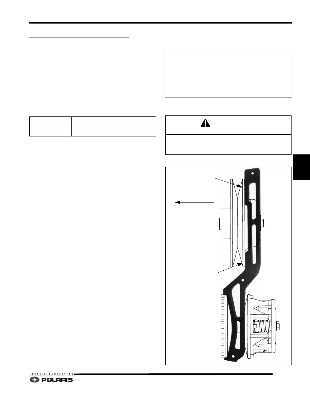
3. The optimum setup is when the front and rear of the
too
l touch the driven clutch. No gap should be present
in the front, and the rear clearance should not exceed
.060" (1.5mm).
NOTE: If the front of the alignment bar does not touch
t
he driven sheave, the maximum clearance cannot
exceed .025
(.64mm).
Offset/Float Adjustment
1. Determine direction driven clutch needs to be
adjusted.
2. Remove driven clutch retaining bolt, and remove
dr
iven clutch.
3. With one 16 GA. bushing installed, add or remove
offset washer
s from behind the driven clutch to set the
proper offset.
4. After adjusting the offset, add or remove shim
washe
rs from behind the driven clutch bolt and
washer to provide a .060" (.1.5mm) driven clutch float
on the jackshaft.
AR = As Required
TOOL PART NUMBER APPLICATION
PS-47477 Light Weight (LWT) Team Driven / P2
Driven Clutch Offset/Shim Washers
Offset Washers
16 Gauge Bushing=7556509 (QTY.1)
.023” = 7555917 (AR)
.120” = 7555864 (AR)
Float Washers
.065" = 7555806 (AR)
.105" = 7555832 (AR)
Always verify the driven clutch floats on the jackshaft.
The jackshaft bearing will fail from side-loading if the
driven clutch is not allowed to float.
0” - .060”
TOUCHING
(PN: PS-46998 Shown)
PUSH CLUTCH

 Loading...


