5.23
Final Drive/Brake System
5
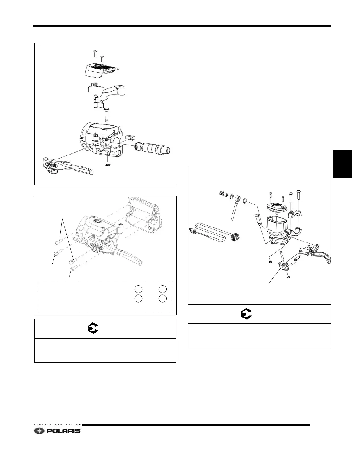
Combined Master Cylinder/Lever Service
Switch Pack Screw Location/Torque Sequence:
1. To remove the brake lever, remove the e clip from the
lev
er pin.
2. Extract the pin from the housing, then remove the
lev
er.
3. To remove the parking brake lever, the housing cover
mu
st be removed. Once removed, carefully extract
the spring noting it its position inside the housing.
Remove the parking brake lever.
4. To remove the cartridge, completely drain the brake
flu
id from the housing. Remove the brake and parking
brake levers.
5. Disconnect the brake hose from the cartridge.
Ca
refully pop the cartridge out of the housing.
6. To install the cartridge, lubricate the entire surface
with DOT 4 br
ake fluid.
7. Align the cartridge with the housing tabs, then firmly
p
ress the cartridge back into the housing until the
cartridge is engaged with the tabs.
8. Refill and bleed the brakes system as
outlined in this
chapter. See “Brake Fluid Replacement & Bleeding”
on page 5.22.
9. Test brake system prior to returning vehicle to service.
Cyclone Master Cylinder/Lever Service
Cover Screws: 16-20 in-lbs (1.8-2.3Nm)
Switch Pack Screws: 25-30 in-lbs (2.8-3.4Nm)
Brake Hose: 240-264 in-lbs (27-30Nm)
COVER SCREWS
COVER
PARKING BRAKE LEVER
CARTRIDGE
BRAKE LEVER
LEVER PIN
E CLIP
SWITCH
#10x.75 SCREWS
#10x1.12 SCREW
#10x1.5 SCREW
TOP
TORQUE SEQUENCE
12
4
3
Torque upper two screws until gap is closed.
Torque bottom two screws to specification.
Test MODE/SET switch for binding.
If switch binds, loosen bottom two screws evenly
until binding stops. Maintain a closed gap at the top.
Cover Screws: 6-8 in-lbs (.7-.9Nm)
Handlebar Clamp Screws: 60-80 in-lbs (6.8-9Nm)
Brake Hose Banjo Screw: 240-264 in-lbs (27-30Nm)
PARKING BRAKE LEVER
BRAKE LEVER
LEVER PIN
COVER
COVER SCREWS
CLAMP
CLAMP SCREWS
BRAKE SWITCH
E CLIP
E CLIP

 Loading...


