10.5
Battery and Electrical Systems
10
Rider Information Display
The rider information display is located in the instrument
cluster. All segments will illuminate for approximately one
second at start-up.
NOTE: If the instrument cluster fails to illuminate, an
ov
er-voltage condition may have occurred forcing the
instrument cluster to power down.
1. RPM
/ Vehicle Speed Display - LCD display of either
engine RPM or vehicle speed in MPH or km/h.
2. MPH / km
/h Display - MPH is displayed when the
instrument cluster is in the “Standard” mode. Km/h is
displayed when the instrument cluster is in the “Metric”
mode.
3. Per
formance Information Area - Engine RPM or
Vehicle Speed (whichever is not displayed in top
section of display) / MAX RPM / MAX Ground Speed
and engine temperature (2011 models) are shown in
the middle of the screen. The performance information
area also displays “Play Back” when the play back
function is enabled.
4. Ve
hicle Information Area - Trip meters A and B /
Odometer / Service Interval Hours / Throttle Opening
(TCS). TCS is only available during playback mode.
5. Fu
el Level Indicator - Six segment LCD bar graph
indicating current fuel level. All segments will flash
when the last segment is cleared indicating a low fuel
warning.
6. Chec
k Engine MIL - Illuminated when the ECU has
detected a Diagnostic Trouble Code (DTC) within the
engine management system. Icon will flash when DTC
display mode is active.
7. Engine
Temperature Indicator - LED icon will
illuminate when the ECU determines the engine is
overheating. The icon will flash to indicate the engine
is overheating. The icon will stay lit and not flash if a
severe overheating condition exists.
8. Lo
w Oil Level Indicator - Icon will illuminate when the
oil level in the oil tank becomes too low. Add oil at the
next fuel stop.
9. High Be
am Indicator - LED will illuminate when the
high beam headlamps are active.
10. Par
king Brake Indicator - Icon will illuminate
whenever the brake lever is pulled or when the parking
brake is engaged.
11. Reve
rse Indicator - Icon will illuminate and flash
whenever PERC reverse mode button is pushed on
the LH control.
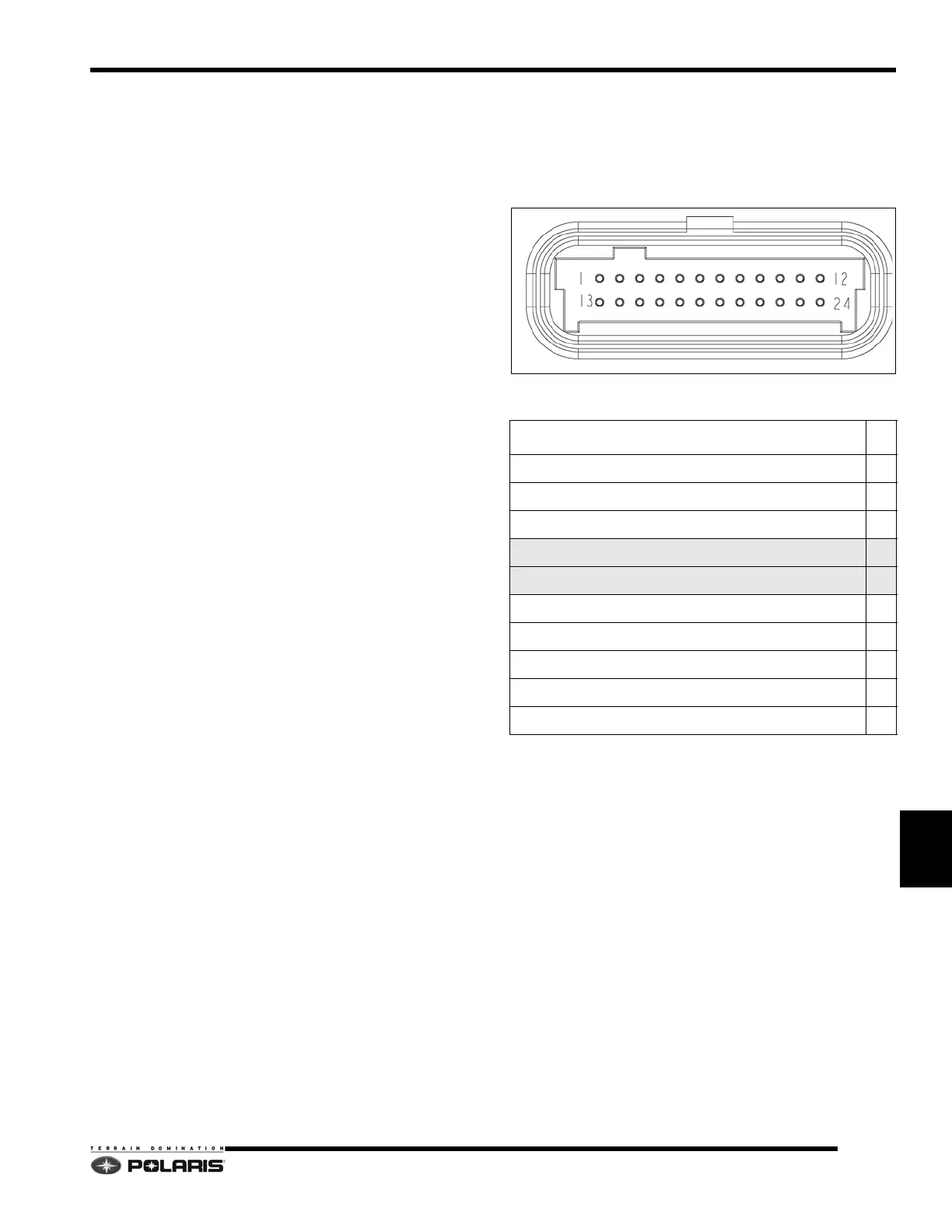
Instrument Cluster Pinouts
NOTE: CAN wires are twisted together and must
remain twisted to prevent interference.
Engine RPM/Vehicle Speed Display
The top section of the display will show either engine
RPM or vehicle speed. If engine RPM is displayed at the
top, then vehicle speed will be displayed in the
performance information area and vice-versa. To change
the top section display, follow these steps:
1. The engine RPM or vehicle speed must be displayed
in the p
erformance information area. If neither is
displayed, press and release the MODE button on the
gauge or LH control until engine RPM or vehicle speed
is displayed.
2. Press and hold the MODE button on the instrument
clust
er or LH control for 3 seconds to switch between
the two displays.
Connector Pinouts
FUNCTION PIN
DC Gauge Voltage (VDC) - RED/WHT 1
Ground - BRN/WHT 2
DC Gauge Voltage (VDC) - RED/WHT
3
CAN 1 High - YELLOW 4
CAN 1 Low - DK GREEN 5
LH Mode Switch - WHT/RED 10
LH Set Switch - WHT/BLK 11
High Beam Signal - YEL/RED 20
Fuel Level Sensor Signal - VIOLET/WHT 23
System Ground - BRN/WHT 24

 Loading...


