10.26
Battery and Electrical Systems
IGNITION TIMING
Timing Procedure
NOTE: Before performing procedure, verify there are
no current trouble codes and that all of the engine
electrical connections are clean and tight.
1. Reference the timing specification chart and locate
th
e piston BTDC measurement for 18°.
2. Install a dial indicator gauge into the MAG spark plug
ho
le.
3. Place the MAG piston at 18° BTDC.
Mark the flywheel.
NOTE: Each 10 degree mark is separated by lines
e
very 2 degree. Acceptable timing variance is +/- 2
degrees.
4. Connect timing light to the engine according to
ma
nufacturer's instructions.
5. Start and run the engine at idle speed until the engine
tem
perature is 120°F (49°C). Verify the throttle lever
is closed and the engine is at idle speed (1700 +/- 100
RPM).
NOTE: The engine temperature must be
a
pproximately 120°F (49°C) to obtain accurate timing
specification.
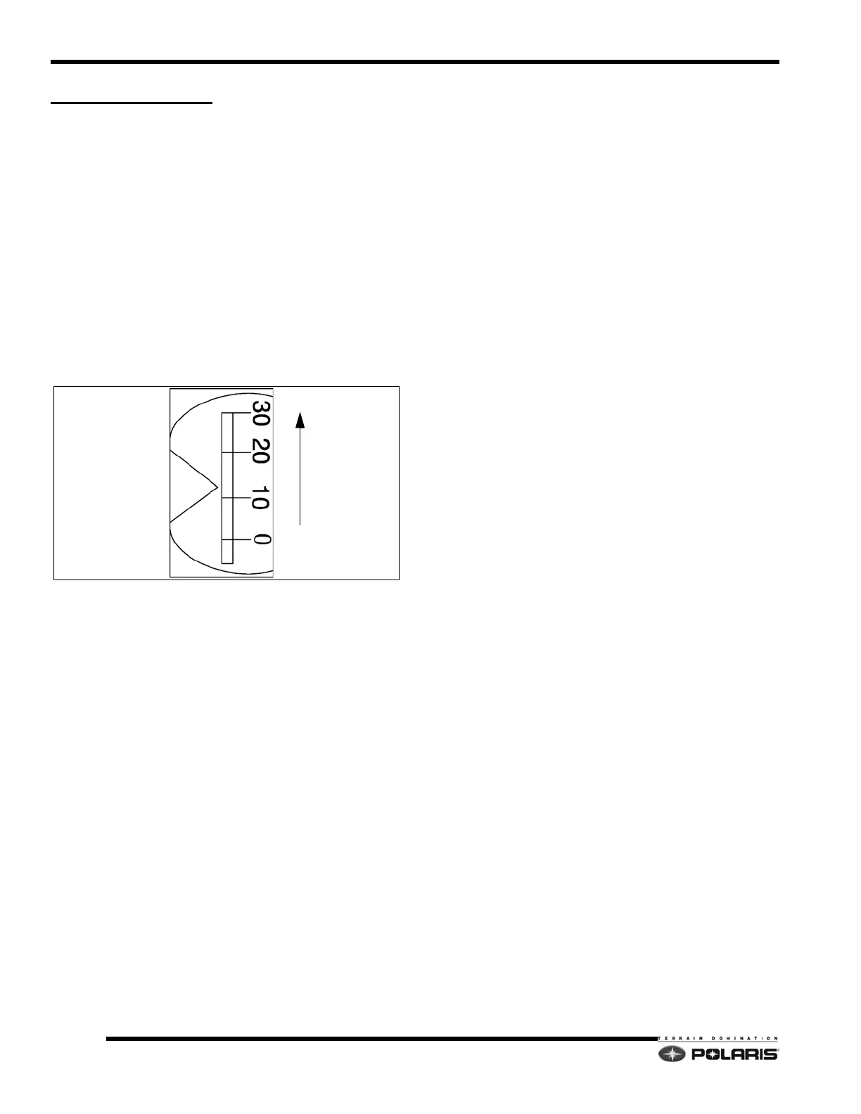
6. Point the timing light at the timing inspection hole.
7. With your head positioned so there is a straight line
b
etween your eye, the stationary pointer and the
crankshaft center line, note the relative position
between the marked flywheel line and the pointer. If
the stationary pointer is aligned with the mark made
in Step 3, or within the acceptable variance, ignition
timing is correct.
NOTE: The stator plate, two-tooth, and five-tooth
c
rankshaft position sensor locations are not
adjustable.
8. If the pointer is outside the variance, either the
f
lywheel key has sheared allowing the flywheel to
move on the crankshaft, the crankshaft is out of index,
a problem with the engine electrical harness exists, or
one of the crankshaft position sensors has moved.

 Loading...


