5.25
Final Drive/Brake System
5
14. On combined master cylinders, place the switch pack
with the master cylinder onto the handle bar. Two
smaller screws should be placed on the top and the
longest screw is placed on the lower right.
15. Follow the bleeding procedure. See “Brake Fluid
Replacement & Bleeding” on page 5.22.
16. Test brake system prior to returning vehicle to service.
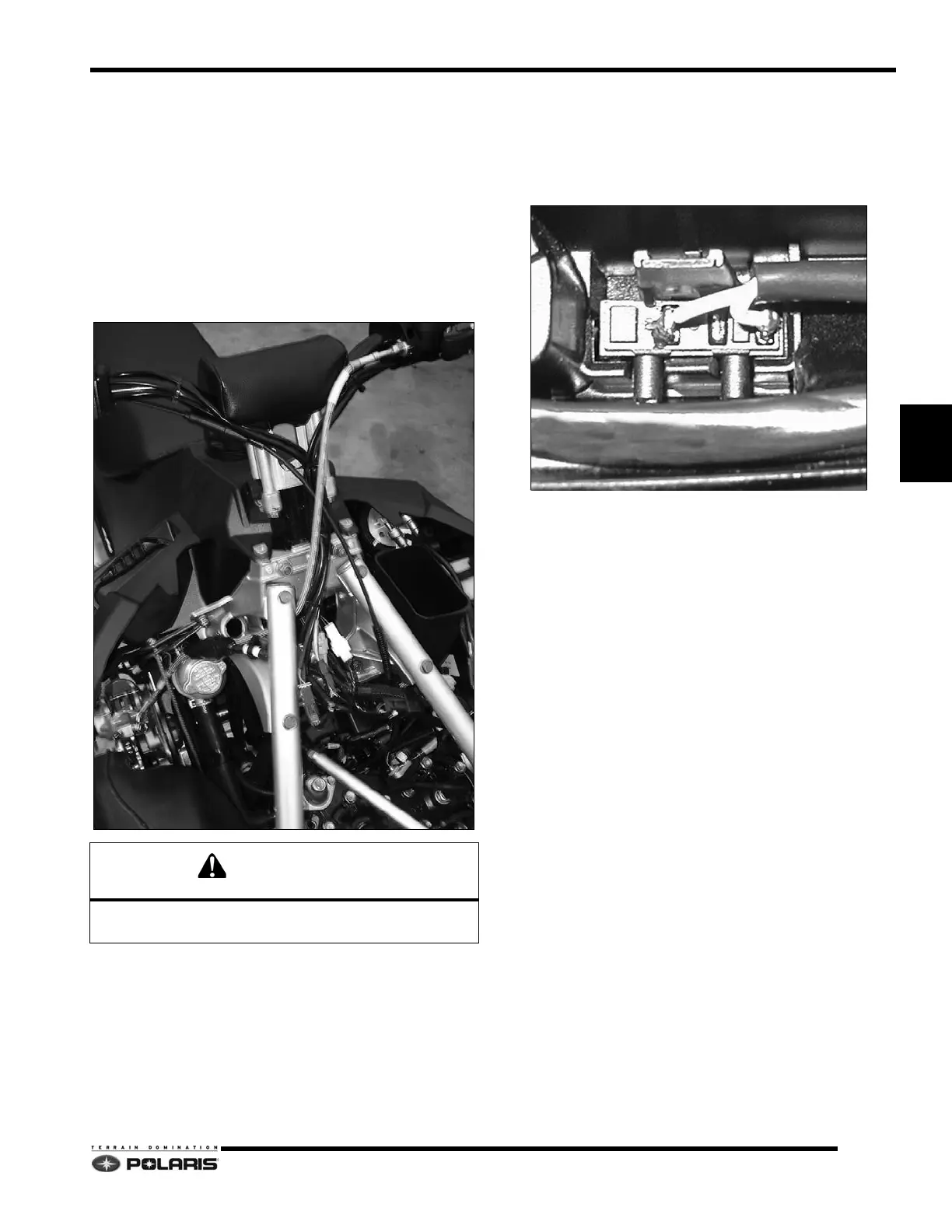
Brake Hose Routing
Route brake hose over steering block, under right over
structure tube, and behind coolant surge tank.
Combined MC Brake Light Switch
Replacement
1. Remove the 4 screws that hold the master cylinder to
the handlebar. This will separate the master cylinder
from the switch pack.
2. Unplug the brake light switch harness from the master
cylinder.
3. Replace faulty brake light switc
h into the master
cylinder and route wires correctly.
4. Plug the brake switch back into the harness.
5. Replace the master cylinder to the switch pack and
in
sert the smaller screws on the top, the longest one
goes into the lower right side.
Do not pinch brake hose between over structure tubes
and steering block or between hood and hood mounts.

 Loading...


