2.12
Maintenance
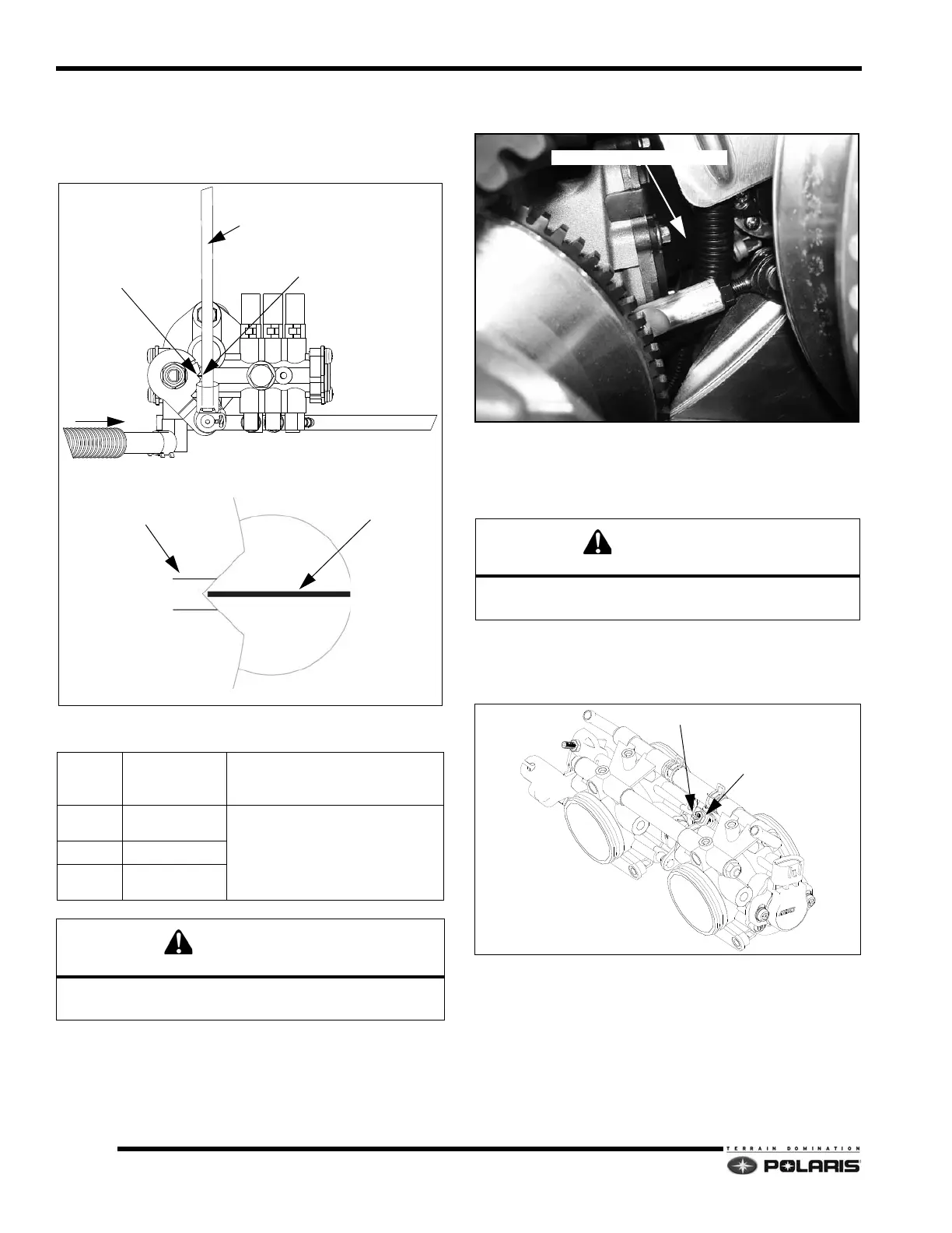
Oil Pump Adjustment
1. Verify the throttle cable free play is set to specification
(.010 - .030) and the throttle lever is synchronized to
the throttle plates.
2. Remove the following components:
• Left side compartment door panel
3. Access to the oil pump for inspection is between the
drive
and driven clutches.
4. Using a mirror and a flash light, visually inspect the
cu
rrent oil pump setting. The scribe mark should be
aligned with the point of the lever notch when the
throttle plates are closed.
5. If adjustment is required, locate
the oil pump linkage
adjuster on the throttle body. Open and release the
throttle several times to verify throttle plates are
closed.
6. Loosen the adjuster jam nut. Using an Allen wrench,
tu
rn the adjuster screw clockwise to raise the oil pump
lever arm. Turn the screw counter-clockwise to lower
the oil pump lever arm.
7. Visually inspect the lever notch/scribe mark
align
ment. When in alignment, tighten the jam nut
without moving the adjuster screw.
Oil Pump Adjustment Settings
PART
NUMBER
ARM
MARKING LEVER SETTING
2521000
1204439
600B
Set lever notch in-line with oil pump scribe
mar
k.
1204695 600C
1204363
1
204438
800B
Failure to properly set the oil pump lever arm may cause
severe engine damage.
LINKAGE ARM
OIL SUPPLY
LEVER NOTCH
SCRIBE MARK
SCRIBE MARK
SCRIBE MARK ALIGNED TO
CENTER OF NOTCH +/-
WIDTH OF SCRIBE MARK
The oil pump lever and pump boss marks must be
observed straight-on to yield accurate results.
LOOK THROUGH THIS OPENING

 Loading...


