RL78/G13 CHAPTER 29 ELECTRICAL SPECIFICATIONS
R01UH0146EJ0100 Rev.1.00 1041
Sep 22, 2011
Caution The pins mounted depend on the product. Refer to 2.1.1 20-pin products to 2.1.14 128-pin products,
and 2.1.15 Pins for each product (pins other than port pins).
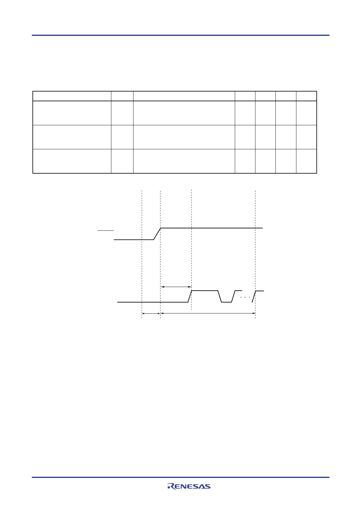
29.10 Timing Specs for Switching Modes
Parameter Symbol Conditions MIN. TYP. MAX. Unit
How long from when a pin reset
ends until the initial communication
settings are specified
t
SUINIT
POR and LVD reset must end before the pin
reset ends.
100 ms
How long from when the TOOL0
pin is placed at the low level until a
pin reset ends
t
SU
POR and LVD reset must end before the pin
reset ends.
10
μ
s
How long the TOOL0 pin must be
kept at the low level after a reset
ends
t
HD
POR and LVD reset must end before the pin
reset ends.
1 ms
<1>
<2>
<3>
RESET
TOOL0
t
SUINIT
t
HD
+
software
processing
time
<4>
t
SU
<1> The low level is input to the TOOL0 pin.
<2> The pins reset ends (POR and LVD reset must end before the pin reset ends.).
<3> The TOOL0 pin is set to the high level.
<4> Setting of the flash memory programming mode by UART reception and complete the baud
rate setting.
Remark t
SUINIT: The segment shows that it is necessary to finish specifying the initial communication settings within 100
ms from when the external and internal resets end.
t
SU: How long from when the TOOL0 pin is placed at the low level until a pin reset ends
t
HD: How long to keep the TOOL0 pin at the low level from when the external and internal resets end
<R>
<R>
<R>
<R>

 Loading...


