RL78/G13 CHAPTER 2 PIN FUNCTIONS
R01UH0146EJ0100 Rev.1.00 52
Sep 22, 2011
2.1.6 36-pin products
(1/2)
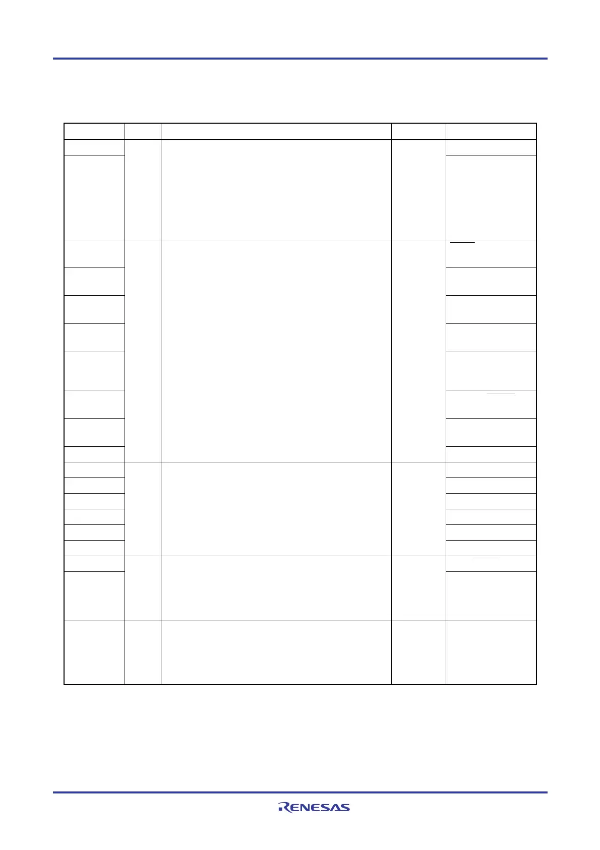
Function Name I/O Function After Reset Alternate Function
P00 TI00/TxD1
P01
I/O
Port 0.
2-bit I/O port.
Input of P01 can be set to TTL input buffer.
Output of P00 can be set to N-ch open-drain output (V
DD
tolerance).
Input/output can be specified in 1-bit units.
Use of an on-chip pull-up resistor can be specified by a
software setting.
Input port
TO00/RxD1
P10
SCK00/SCL00
(TI07)/(TO07)
P11
SI00/RxD0/TOOLRxD/
SDA00/(TI06)/(TO06)
P12
SO00/TxD0/TOOLTxD
/(TI05)/(TO05)
P13
TxD2/SO20/(SDAA0)/
(TI04)/(TO04)
P14
RxD2/SI20/SDA20/
(SCLA0)/(TI03)/
(TO03)
P15
PCLBUZ1/SCK20/
SCL20/(TI02)/(TO02)
P16
TI01/TO01/INTP5/
(RxD0)
P17
I/O
Port 1.
8-bit I/O port.
Input of P10, P11, and P13 to P17 can be set to TTL input
buffer.
Output of P10 to P15, and P17 can be set to N-ch open-drain
output (V
DD tolerance).
Input/output can be specified in 1-bit units.
Use of an on-chip pull-up resistor can be specified by a
software setting.
Input port
TI02/TO02/(TxD0)
P20 ANI0/AVREFP
P21 ANI1/AVREFM
P22 ANI2
P23 ANI3
P24 ANI4
P25
I/O
Port 2.
6-bit I/O port.
Input/output can be specified in 1-bit units.
Analog input
port
ANI5
P30 INTP3/SCK11/SCL11
P31
I/O
Port 3.
2-bit I/O port.
Input/output can be specified in 1-bit units.
Use of an on-chip pull-up resistor can be specified by a
software setting.
Input port
TI03/TO03/INTP4/PCL
BUZ0
P40 I/O
Port 4.
1-bit I/O port.
Input/output can be specified.
Use of an on-chip pull-up resistor can be specified by a
software setting.
Input port TOOL0
Remark Functions in parentheses in the above figure can be assigned via settings in the peripheral I/O redirection
register (PIOR).
<R>

 Loading...


