RL78/G13 CHAPTER 9 CLOCK OUTPUT/BUZZER OUTPUT CONTROLLER
R01UH0146EJ0100 Rev.1.00 464
Sep 22, 2011
9.2 Configuration of Clock Output/Buzzer Output Controller
The clock output/buzzer output controller includes the following hardware.
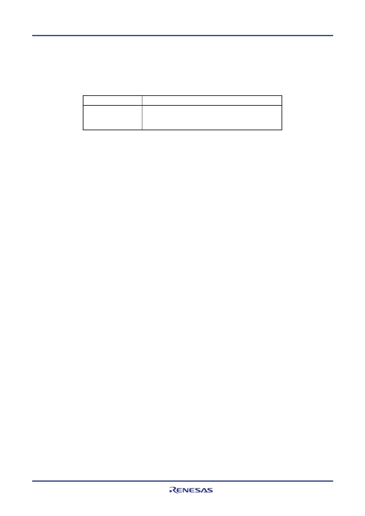
Table 9-1. Configuration of Clock Output/Buzzer Output Controller
Item Configuration
Control registers
Clock output select registers n (CKSn)
Port mode register 1, 3, 5, 14 (PM1, PM3, PM5, PM14)
Port register 1, 3, 5, 14 (P1, P3, P5, P14)
9.3 Registers Controlling Clock Output/Buzzer Output Controller
The following two registers are used to control the clock output/buzzer output controller.
• Clock output select registers n (CKSn)
• Port mode register 1, 3, 5, 14 (PM1, PM3, PM5, PM14)
(1) Clock output select registers n (CKSn)
These registers set output enable/disable for clock output or for the buzzer frequency output pin (PCLBUZn), and
set the output clock.
Select the clock to be output from the PCLBUZn pin by using the CKSn register.
The CKSn register are set by a 1-bit or 8-bit memory manipulation instruction.
Reset signal generation clears these registers to 00H.

 Loading...


