RL78/G13 CHAPTER 5 CLOCK GENERATOR
R01UH0146EJ0100 Rev.1.00 282
Sep 22, 2011
CHAPTER 5 CLOCK GENERATOR
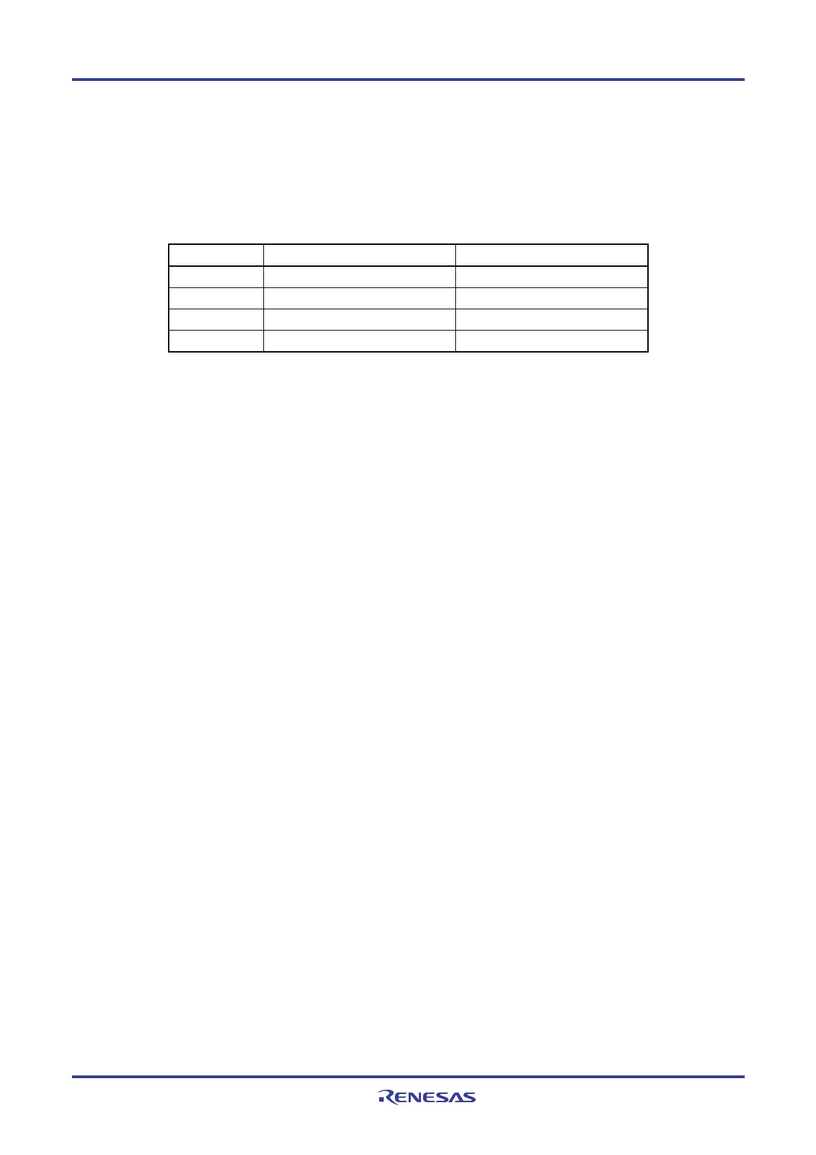
The presence or absence of connecting resonator pin for main system clock, connecting resonator pin for subsystem
clock, external clock input pin for main system clock, and external clock input pin for subsystem clock, depends on the
product.
Output pin 20, 24, 25, 30, 32, 36-pin 40, 44, 48, 52, 64, 80, 100, 128-pin
X1, X2 pins
√ √
EXCLK pin
√ √
XT1, XT2 pins
− √
EXCLKS pin
− √
Note The 20, 24, 25, 30, 32, and 36-pin products don’t have the subsystem clock.
5.1 Functions of Clock Generator
The clock generator generates the clock to be supplied to the CPU and peripheral hardware.
The following three kinds of system clocks and clock oscillators are selectable.
(1) Main system clock
<1> X1 oscillator
This circuit oscillates a clock of f
X = 1 to 20 MHz by connecting a resonator to X1 and X2.
Oscillation can be stopped by executing the STOP instruction or setting of the MSTOP bit (bit 7 of the clock
operation status control register (CSC)).
<2> High-speed on-chip oscillator (High-speed OCO)
The frequency at which to oscillate can be selected from among f
IH = 32, 24, 16, 12, 8, 4, or 1 MHz (typ.) by
using the option byte (000C2H). After a reset release, the CPU always starts operating with this high-speed
on-chip oscillator clock. Oscillation can be stopped by executing the STOP instruction or setting the
HIOSTOP bit (bit 0 of the CSC register).
An external main system clock (f
EX = 1 to 20 MHz) can also be supplied from the EXCLK/X2/P122 pin. An external
main system clock input can be disabled by executing the STOP instruction or setting of the MSTOP bit.
As the main system clock, a high-speed system clock (X1 clock or external main system clock) or high-speed on-
chip oscillator clock can be selected by setting of the MCM0 bit (bit 4 of the system clock control register (CKC)).

 Loading...


