86
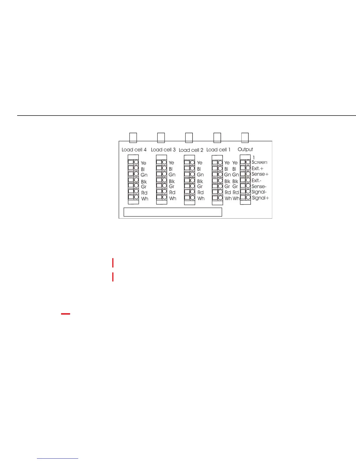
Pin Assignments in the Junction Box
Color Codes: Load Cell Cables and Connecting Cable
(Weighing Platform to the Junction Box) (Junction Box to A/D Converter)
Load cell 1-4 Output
Ye (yellow) = Ye (yellow) = Shield = Ye (yellow)
Bl (blue) = Gn (green) = (1) BR_POS (Bridge supply voltage +) = Bl (blue)
Gn (green) = ---- = (2) SENSE_POS (Sense +) = Gn (green)
Blk (black) = Blk (black) = (6) (BR_NEG (Bridge supply voltage -) = Blk (black) or (brown)
Gr (gray) = ---- = (5) SENSE_NEG (Sense -) = Gr (gray)
Rd (red) = Rd (red) = (4) OUT_NEG (Measuring voltage negative) = Rd (red)
Wh (white) = Wh (white) = (3) OUT_POS (Measuring voltage positive) = Wh (white)
(Wiring Bridge )
Note: The color coding of the connecting cable (junction box to A/D converter) might be
different when connecting a non-Sartorius platform to the Combics indicator.
kabelan1_e.gif
adjustment resistor
 Loading...