48/219
Building Technologies Basic Documentation LMV27... CC1P7541en
7 Basic unit LMV27 17.12.2018
7.5 Program sequence
The program sequence is shown in the form of sequence diagrams (refer to chapter
Fuel trains). Using a number of parameters, the program sequence can be adapted to
the respective application.
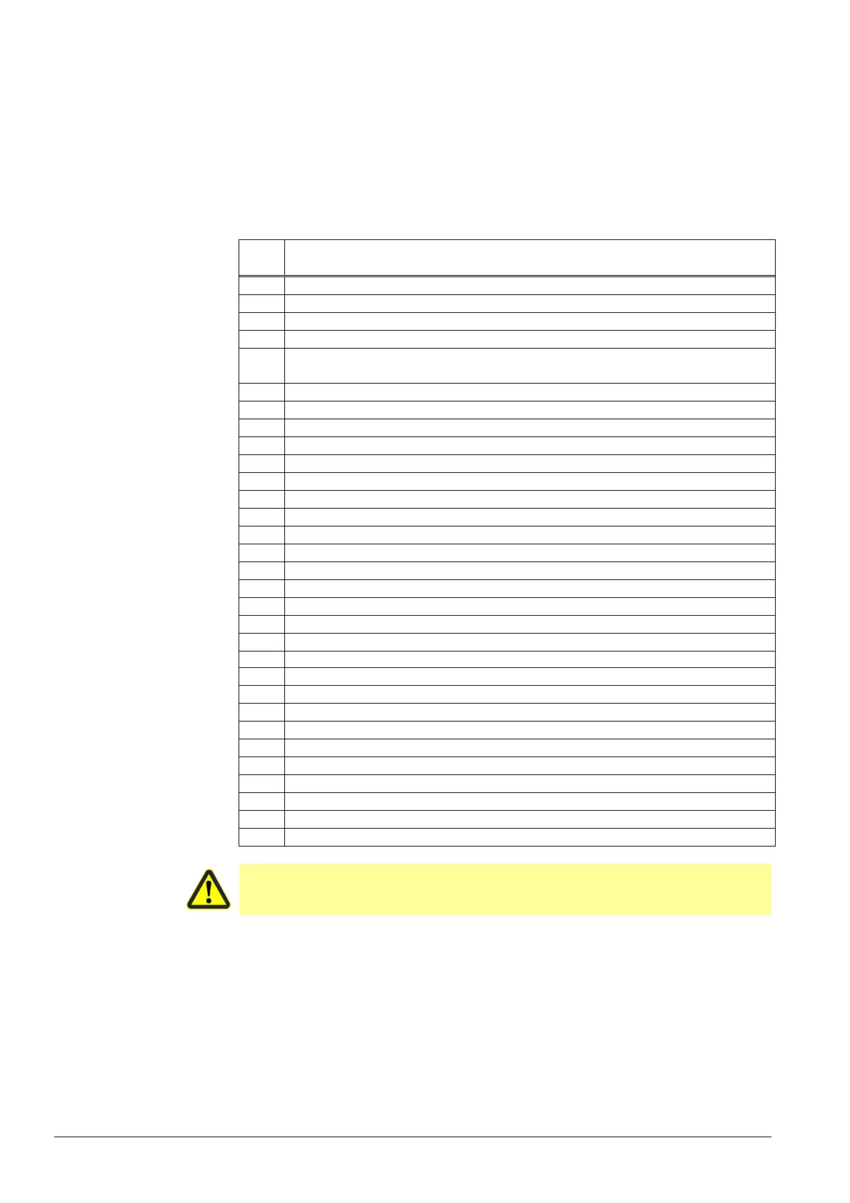
7.5.1 Time parameters
Using a number of time parameters, the time characteristics of the different types of fuel
trains can be matched to the requirements of the respective application.
No. Parameter
211 Fan rump-up time
212 Maximum time to low-fire
213 Waiting time home run
214 Maximum time to start release
217
Max. Waiting time for detection of detector or pressure signal (e.g. homerun,
preignition «Lo»)
225 Gas: Prepurge time
226 Gas: Preignition time
227 Gas: First safety time
229 Gas: Time to respond to pressure faults in the first and second safety time
230 Gas: Interval 1
231 Gas: Second safety time
232 Gas: Interval 2
233 Gas: Afterburn time
234 Gas: Postpurge time (no extraneous light test)
242 Gas: Valve proving - test space evacuating
243 Gas: Valve proving - test time atmospheric pressure
244 Gas: Valve proving - test space filling
245 Gas: Valve proving - test time gas pressure
246 Gas: Waiting time gas shortage
248 Gas: Postpurge time (abortion if load controller ON)
249 Gas: Prepurge time (OEM)
265 Oil: Prepurge time
266 Oil: Preignition time
267 Oil: First safety time
269 Oil: Time to respond to pressure faults in the first and second safety time
270 Oil: Interval 1
271 Oil: Second safety time
272 Oil: Interval 2
273 Oil: Afterburn time
274 Oil: Postpurge time (no extraneous light test)
284 Oil: Postpurge time (abortion if load controller ON)
Caution!
The OEM or the heating engineer must make certain that the times conform to
the standards covering the respective type of plant.

 Loading...