96/219
Building Technologies Basic Documentation LMV27... CC1P7541en
10 Electronic air-fuel ratio control 17.12.2018
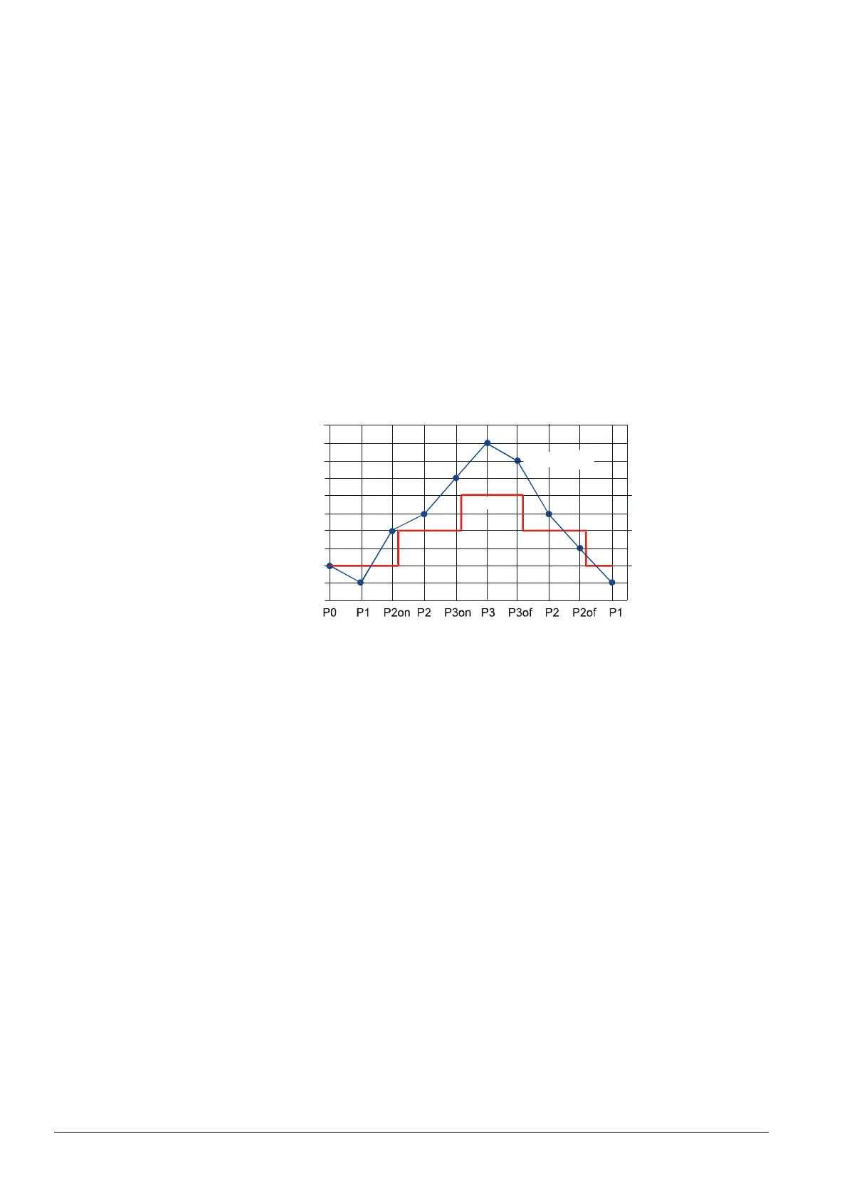
10.4.3 Adjustment of output
When the output increases, the LMV27 moves from the curvepoint of stage 1 (P1) to the
switch-on point of stage 2 (P2on). If the switch-on point is exceeded, the valve for the
second stage is switched on. Then, the LMV27 moves to the curvepoint for stage 2 (P2).
When the output decreases, the LMV27 moves from the curvepoint of stage 2 (P2) to
the switch-off point of stage 2 (P2of). If this point is crossed, the valve for the second
stage is switched off. Then, the LMV27 moves to the curvepoint for stage 1 (P1).
In 3-stage operation, the output between stage 2 and stage 3 is adjusted analogously to
2-stage operation. As static outputs, only P1, P2 and P3 can be approached.
The switch-on and switch-off points are crossed only when changing between stages.
The traveling speeds are fixed. Depending on the positioning angles to be covered, air
actuator does not reach the operating or switch-on / switch-off points at the same time.
The valves are switched on / off only after both actuators have reached their correct
positions.
When parameterizing the curves, the switch-on points can also be approached in a
stationary manner. In addition, when setting the curve via P2_d (P3_d), curvepoint P2
(P3) can be readjusted without traveling to it. In that case, the LMV27 is at the
respective switch-on point. This procedure is used to reduce the operating time if there
is shortage of air.
V3
V2
V1
Valve
Bild 225e/1010
Air actuator
10 V (100 %)
(90 %)
2 V (10° / 10 %)
0
Figure 65: Adjustment of output
10.4.4 Entering the operating position
The burner is ignited at ignition position P0. When entering operating phase 60, the
actuators are driven from ignition position P0 to the operating point of stage 1 (P1) at the
respective traveling speed.
10.4.5 Operating position
In the operating position, the burner’s output can be adjusted between operating points
P1 and P2 or P3 in accordance with the load controller’s presetting, as described in
chapter Adjustment of output. Ignition position P0 is not approached anymore. It can
only be reached via curve adjustment.

 Loading...